FUEL INJECTOR(for Direct Injection) REMOVAL

CAUTION / NOTICE / HINT
The necessary procedures (adjustment, calibration, initialization or registration) that must be performed after parts are removed and installed, or replaced during fuel injector assembly removal/installation are shown below.
| Replaced Part or Performed Procedure | Necessary Procedure | Effect/Inoperative Function when Necessary Procedure not Performed | Link |
|---|---|---|---|
| Battery terminal is disconnected/reconnected | Memorize steering angle neutral point | LKA/LDA System | |
| Pre-crash safety system | |||
| Lighting system (EXT)
|
|||
| Adaptive high beam system | |||
| Drive the vehicle until stop and start control is permitted (approximately 15 to 60 minutes) | Stop and start system | ||
| Memorize steering angle neutral point | Parking Assist Monitor System (w/ Parallel Parking Assist Function) | ||
| Parking Assist Monitor System (w/o Parallel Parking Assist Function) | |||
| Panoramic view monitor system | |||
| Initialize back door lock | Power door lock control system | ||
| Reset back door close position | Power back door system | ||
|
Inspection After Repair |
|
w/ Canister Pump Module: Click here w/o Canister Pump Module: Click here |
PROCEDURE
-
REMOVE FUEL PUMP ASSEMBLY (for High Pressure)
-
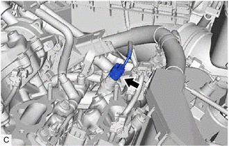
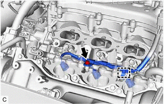
REMOVE NO. 2 FUEL PIPE SUB-ASSEMBLY
CAUTION:
To prevent serious injury due to fuel spray from the high-pressure fuel lines, always discharge fuel system pressure before removing any fuel system components.
-
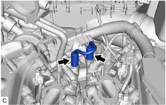
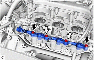
Using a 17 mm union nut wrench, loosen the 2 union nuts of the No. 2 fuel pipe sub-assembly.
-
Remove the No. 2 fuel pipe sub-assembly from the fuel delivery pipe with sensor assembly LH and fuel delivery pipe RH.
-
-
REMOVE WIRE HARNESS CLAMP BRACKET
-
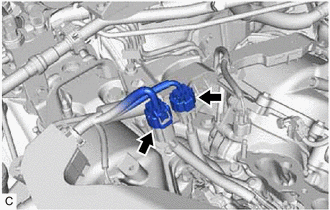
Disconnect the No. 6 engine wire connector and No. 7 engine wire connector.
-
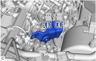
Disengage the 2 clamps to remove the wire harness clamp bracket.
-
-
REMOVE FUEL DELIVERY PIPE WITH SENSOR ASSEMBLY LH
-
Disconnect the fuel pressure sensor connector.
-
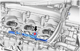
Remove the bolt.
-
Disengage the clamp to disconnect the No. 7 engine wire from the fuel delivery pipe with sensor assembly LH.
-
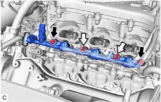

Bolt 
Nut Remove the 2 bolts, 2 nuts and fuel delivery pipe with sensor assembly LH with the fuel injector assemblies.
Note
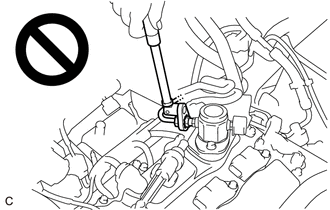
-
Make sure not to touch or strike the tips of the fuel injector assemblies.
-
Pull and remove the fuel delivery pipe with sensor assembly LH in a straight line without tilting it.
-
-
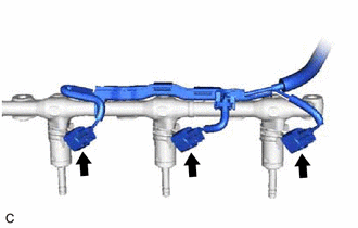
Disconnect the 3 fuel injector assembly connectors.
-
-
REMOVE FUEL DELIVERY PIPE RH
-
Remove the bolt.
-
Disengage the clamp to disconnect the No. 6 engine wire from the fuel delivery pipe RH.
-
Bolt Nut Remove the 2 bolts, 2 nuts and fuel delivery pipe RH with the fuel injector assemblies.
Note
-
Make sure not to touch or strike the tips of the fuel injector assemblies.
-
Pull and remove the fuel delivery pipe RH in a straight line without tilting it.
-
-
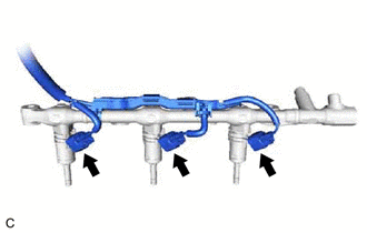
Disconnect the 3 fuel injector assembly connectors.
-
-
REMOVE FUEL INJECTOR ASSEMBLY
-
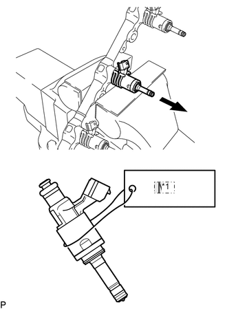
*1 No. 2 Secure the fuel delivery pipe with sensor assembly LH and fuel delivery pipe RH in a vise between aluminum plates and pull out the 6 fuel injector assemblies.
Note
-
Pull and remove each fuel injector assembly in a straight line to avoid damaging the seal surface of the fuel delivery pipe with sensor assembly LH and fuel delivery pipe RH O-ring.
-
After removing the fuel injector assemblies, remove any O-rings, No. 1 fuel injector back-up rings and No. 3 fuel injector back-up rings remaining on the fuel delivery pipe with sensor assembly LH and fuel delivery pipe RH side.
-
Attach a tag or label with the corresponding cylinder number to each fuel injector assembly so that they can be installed to their original locations.
-
-
Remove the nozzle holder clamp from each fuel injector assembly.
-
Using needle nose pliers, remove the No. 3 fuel injector back-up ring from each fuel injector assembly.
Note
Do not damage the area that contacts the O-ring.
-
Remove the O-ring and No. 1 fuel injector back-up ring from each fuel injector assembly.
-
Remove the C-ring and injector vibration insulator from each fuel injector assembly.
-
-
REMOVE FUEL INJECTOR SEAL
-
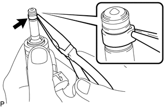
Using the tip of needle nose pliers, pinch and pull the fuel injector seal at several points to stretch it.
Note
-
Excessively pinching the fuel injector seal may damage the groove of the fuel injector assembly.
-
If a fuel injector assembly is dropped or the tip of the fuel injector assembly is struck, replace it with a new one.
-
-
Remove the fuel injector seal from each fuel injector assembly.
-