VEHICLE STABILITY CONTROL SYSTEM Slip Indicator Light Remains ON
DESCRIPTION
If the skid control ECU (brake actuator assembly) stores a DTC, the slip indicator light in the combination meter comes on.
The slip indicator light blinks during VSC and TRC operation.
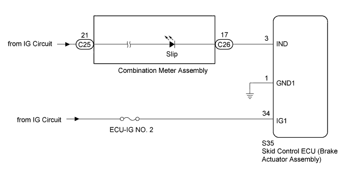
WIRING DIAGRAM
INSPECTION PROCEDURE
Note
-
After replacing the brake actuator assembly, perform calibration Click here.
-
Before disconnecting the connector, make sure that there are no problems with the connection.
-
After disconnecting the connector, make sure that the connector case and terminals are not deformed or corroded.
PROCEDURE
-
CHECK FOR DTC
-
Check if DTCs for the VSC are output Click here.
Result Result Proceed to DTC is not output A DTC is output B
B 
REPAIR CIRCUITS INDICATED BY OUTPUT DTCS Click here
A 
-
-
PERFORM ACTIVE TEST USING INTELLIGENT TESTER (SLIP INDICATOR LIGHT)
-
Turn the ignition switch off.
-
Connect the intelligent tester to the DLC3.
-
Turn the ignition switch to ON.
-
Turn the intelligent tester on.
-
Enter the following menus: Chassis / ABS/VSC/TRC / Active Test.
ABS/VSC/TRC Tester Display Test Part Control Range Diagnostic Note Slip Indicator Light Slip indicator light Indicator light ON / OFF Observe the combination meter. -
When performing the Slip Indicator Light Active Test, check Slip Indicator Light in the Data List.
ABS/VSC/TRC Tester Display Measurement Item / Range Normal Condition Diagnostic Note Slip Indicator Light Slip indicator light /
ON or OFF
ON: Slip indicator light on
OFF: Slip indicator light off
- Result Result Proceed to Data List Display Data List Display When Performing Active Test ON/OFF Operation ON Does not change between ON and OFF for LHD A Does not change between ON and OFF for RHD B Changes between ON and OFF C OFF Does not change between ON and OFF for LHD A Does not change between ON and OFF for RHD B Changes between ON and OFF C
B
REPLACE BRAKE ACTUATOR ASSEMBLY Click here
C 
CHECK HARNESS AND CONNECTOR (SKID CONTROL ECU - COMBINATION METER) Click here
A 
REPLACE BRAKE ACTUATOR ASSEMBLY Click here
-
-
CHECK HARNESS AND CONNECTOR (SKID CONTROL ECU - COMBINATION METER)
-
Turn the ignition switch off.
-
Disconnect the skid control ECU (brake actuator assembly) connector.
-
Disconnect the C26 combination meter connector.
-
Measure the resistance according to the value(s) in the table below.
Standard Resistance Tester Connection Condition Specified Condition S35-3 (IND) - C26-17 Always Below 1 Ω S35-3 (IND) - Body ground Always 10 kΩ or higher
NG
REPAIR OR REPLACE HARNESS OR CONNECTOR
OK
GO TO METER / GAUGE SYSTEM (HOW TO PROCEED WITH TROUBLESHOOTING) Click here
-