ECD SYSTEM (w/o EGR Cooler), Diagnostic DTC:P2563, P2564, P2565, P2588, P2589
| DTC Code | DTC Name |
|---|---|
| P2563 | Turbocharger/Supercharger Boost Control Position Sensor "A" Circuit Range/Performance |
| P2564 | Turbocharger/Supercharger Boost Control Position Sensor "A" Circuit Low |
| P2565 | Turbocharger/Supercharger Boost Control Position Sensor "A" Circuit High |
| P2588 | Turbocharger/Supercharger Boost Control Position Sensor "B" Circuit Low |
| P2589 | Turbocharger/Supercharger Boost Control Position Sensor "B" Circuit High |
DESCRIPTION
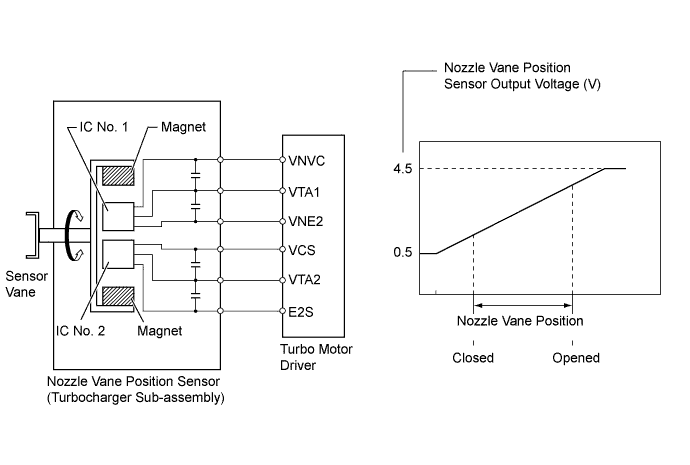
Variable nozzle vane type turbocharger consists primarily of a compressor wheel, turbine wheel, nozzle vane, unison ring, DC motor and nozzle vane position sensor.
The nozzle vane position sensor consists of a Hall IC and a magnetic yoke that rotates in unison with the movement of the linkage that actuates the nozzle vane. The nozzle vane position sensor converts the changes in the magnetic flux that are caused by the rotation of the DC motor (hence, the rotation of the magnetic yoke) into electric signals, and outputs them to the turbo motor driver. The turbo motor driver determines the actual nozzle vane position from the electric signals in order to calculate the target nozzle vane position.
| DTC No. | DTC Detection Condition | Trouble Area |
|---|---|---|
| P2563 | Difference between VTA1 and VTA2 0.8 V or more for 0.5 seconds or more (1 trip detection logic) |
Nozzle vane position sensor (Turbocharger sub-assembly) |
| P2564 | VTA1 0.5 V or less for 0.5 seconds or more (1 trip detection logic) |
|
| P2565 | VTA1 4.5 V or more for 0.5 seconds or more (1 trip detection logic) |
|
| P2588 | VTA2 0.5 V or less for 0.5 seconds or more (1 trip detection logic) |
|
| P2589 | VTA2 4.5 V or more for 0.5 seconds or more (1 trip detection logic) |
|
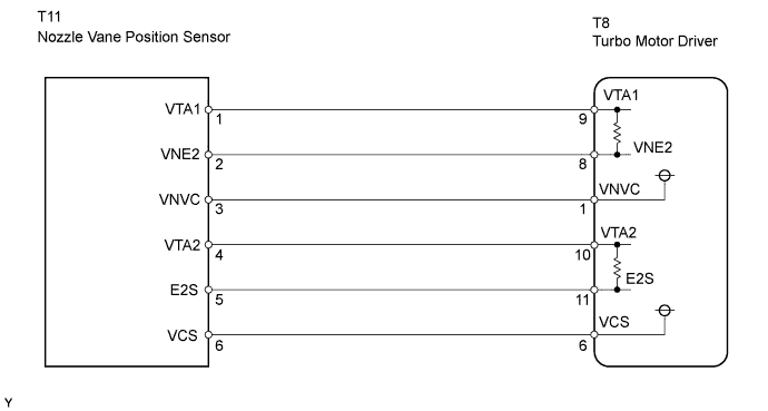
WIRING DIAGRAM
INSPECTION PROCEDURE
Note
After replacing the ECM, the new ECM needs registration Click here and initialization Click here.
Tech Tips
Read freeze frame data using the intelligent tester. Freeze frame data records the engine conditions when a malfunction is detected. When troubleshooting, freeze frame data can help determine if the vehicle was moving or stationary, if the engine was warmed up or not, and other data from the time the malfunction occurred.
PROCEDURE
-
CHECK OTHER DTC OUTPUT (IN ADDITION TO DTC P2563)
-
Connect the intelligent tester to the DLC3.
-
Turn the ignition switch ON and turn the tester ON.
-
Enter the following menus: Powertrain / Engine and ECT / DTC.
-
Read the DTCs.
Result Display (DTC Output) Proceed to P2563, P2564, P2565, P2588 and/or P2589 A P2563, P2564, P2565, P2588 and/or P2589, and other DTCs B
B 
GO TO DTC CHART Click here
A 
-
-
CHECK HARNESS AND CONNECTOR (NOZZLE VANE POSITION SENSOR - TURBO MOTOR DRIVER)
-
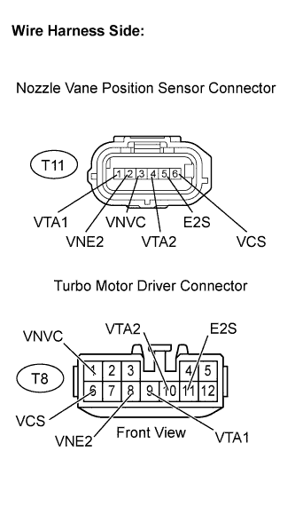
Disconnect the T11 nozzle vane position sensor connector.
-
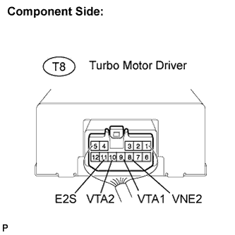
Disconnect the T8 turbo motor driver connector.
-
Measure the resistance of the wire harness side connectors.
Standard resistance (Check for open) Tester Connection Specified Condition VTA1 (T11-1) - VTA1 (T8-9) Below 1 Ω VNE2 (T11-2) - VNE2 (T8-8) Below 1 Ω VNVC (T11-3) - VNVC (T8-1) Below 1 Ω VTA2 (T11-4) - VTA2 (T8-10) Below 1 Ω E2S (T11-5) - E2S (T8-11) Below 1 Ω VCS (T11-6) - VCS (T8-6) Below 1 Ω Standard resistance (Check for short) Tester Connection Specified Condition VTA1 (T11-1) or VTA1 (T8-9) - Body ground 10 kΩ or higher VNE2 (T11-2) or VNE2 (T8-8) - Body ground 10 kΩ or higher VNVC (T11-3) or VNVC (T8-1) - Body ground 10 kΩ or higher VTA2 (T11-4) or VTA2 (T8-10) - Body ground 10 kΩ or higher E2S (T11-5) or E2S (T8-11) - Body ground 10 kΩ or higher VCS (T11-6) or VCS (T8-6) - Body ground 10 kΩ or higher
NG
REPAIR OR REPLACE HARNESS OR CONNECTOR
OK
-
-
INSPECT TURBO MOTOR DRIVER
-
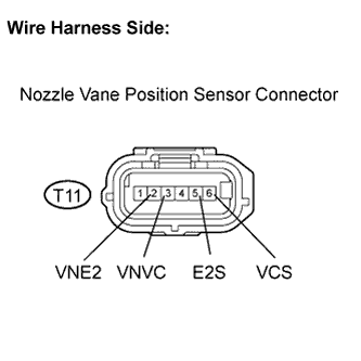
Disconnect the T11 nozzle vane position sensor connector.
-
Turn the ignition switch ON.
-
Measure the voltage between the terminals of the nozzle vane position sensor connector.
Standard voltage Tester Connection Specified Condition VNVC (T11-3) - VNE2 (T11-2) 4.5 to 5.5 V VCS (T11-6) - E2S (T11-5) 4.5 to 5.5 V
NG
REPLACE TURBO MOTOR DRIVER
OK
-
-
INSPECT NOZZLE VANE POSITION SENSOR
-
Turn the ignition switch ON.
-
Measure the voltage between the terminals of the turbo motor driver connector.
Standard voltage Tester Connection Specified Condition VTA1 (T8-9) - VNE2 (T8-8) 0.5 to 4.5 V VTA2 (T8-10) - E2S (T8-11) 0.5 to 4.5 V -
Check the difference between the voltage values.
Result Voltage difference between VTA1 and VTA2 is within 0.8 V
NG
REPLACE TURBOCHARGER SUB-ASSEMBLY (NOZZLE VANE POSITION SENSOR) Click here
OK
-
-
REPLACE TURBO MOTOR DRIVER
NEXT
-
CHECK WHETHER DTC OUTPUT RECURS (P2564, P2565, P2588 AND/OR P2589)
-
Connect the intelligent tester to the DLC3.
-
Turn the ignition switch ON and turn the tester ON.
-
Clear DTCs Click here.
-
Start the engine.
-
Perform the test drive.
-
Enter the following menus: Powertrain / Engine and ECT / DTC.
-
Read the DTCs.
Result Display (DTC output) Proceed to P2563, P2564, P2565, P2588 and/or P2589 is output again A No output B
B
SYSTEM OK
A 
REPLACE TURBOCHARGER SUB-ASSEMBLY Click here
-