AIR CONDITIONING UNIT REMOVAL
CAUTION / NOTICE / HINT
Tech Tips
-
Use the same procedure for RHD and LHD vehicles.
-
The procedure listed below is for LHD vehicles.
-
Use the same procedure for the RH and LH sides.
-
The procedure listed below is for the LH side.
PROCEDURE
-
RECOVER REFRIGERANT FROM REFRIGERATION SYSTEM
-
for HFC-134a(R134a):
-
for HFO-1234yf(R1234yf):
-
-
DRAIN ENGINE COOLANT
-
for 8AR-FTS:
-
for 3ZR-FAE:
-
-
REMOVE NO. 1 ENGINE COVER SUB-ASSEMBLY (for 8AR-FTS)
-
REMOVE NO. 2 CYLINDER HEAD COVER (for 3ZR-FAE)
-
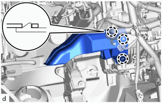
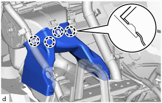
DISCONNECT AIRCONDITIONER TUBE AND ACCESSORY ASSEMBLY (for Sub-cool Accelerator)
-
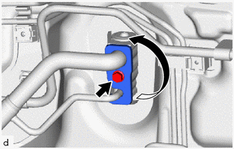
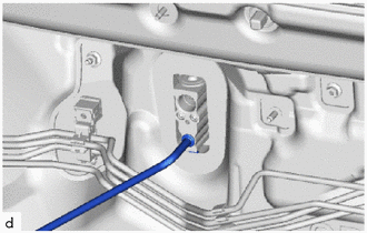
Remove the bolt and rotate the hook connector as shown in the illustration.
-
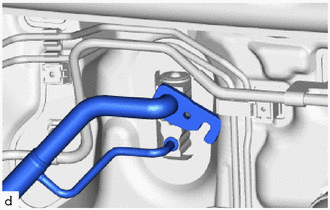
Disconnect the air conditioner tube and accessory assembly.
-
Remove the 2 O-rings from the air conditioner tube and accessory assembly.
Note
Seal the openings of the disconnected parts using vinyl tape to prevent the entry of moisture and foreign matter.
-
-
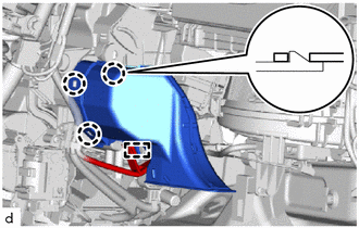
DISCONNECT SUCTION PIPE SUB-ASSEMBLY (except Sub-cool Accelerator)
-
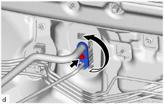
Remove the bolt and rotate the hook connector as shown in the illustration.
-
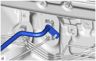
Disconnect the suction pipe sub-assembly.
-
Remove the O-ring from the suction pipe sub-assembly.
Note
Seal the openings of the disconnected parts using vinyl tape to prevent the entry of moisture and foreign matter.
-
-
DISCONNECT LIQUID PIPE SUB-ASSEMBLY (except Sub-cool Accelerator)
-
Disconnect the liquid pipe sub-assembly.
-
Remove the O-ring from the liquid pipe sub-assembly.
Note
Seal the openings of the disconnected parts using vinyl tape to prevent the entry of moisture and foreign matter.
-
-
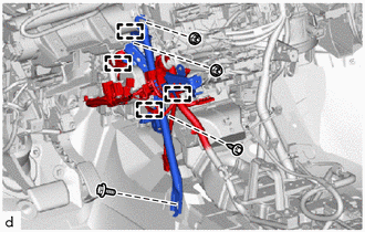
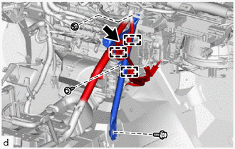
DISCONNECT HEATER WATER OUTLET HOSE A
-
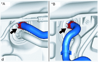
*A for 8AR-FTS *B for 3ZR-FAE Using pliers, grip the claws of the clip and slide the clip to disconnect the heater water outlet hose A.
Note
-
Do not apply excessive force to the water hose and heater water outlet hose A.
-
Prepare a drain pan or cloth in case the coolant leaks.
-
-
-
DISCONNECT WATER HOSE SUB-ASSEMBLY B
-
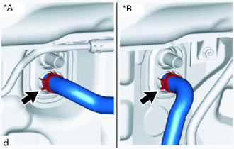
*A for 8AR-FTS *B for 3ZR-FAE Using pliers, grip the claws of the clip and slide the clip to disconnect the water hose sub-assembly B.
Note
-
Do not apply excessive force to the water hose and water hose sub-assembly B.
-
Prepare a drain pan or cloth in case the coolant leaks.
-
-
-
REMOVE LOWER INSTRUMENT PANEL
-
REMOVE STEERING COLUMN ASSEMBLY (for Manual Tilt and Manual Telescopic Steering Column)
-
REMOVE STEERING COLUMN ASSEMBLY (for Power Tilt and Power Telescopic Steering Column)
-
REMOVE LOWER DEFROSTER NOZZLE ASSEMBLY
-
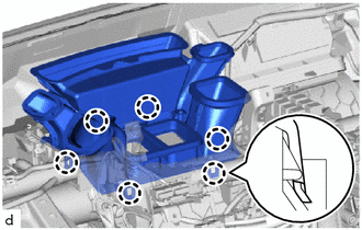
Detach the 6 claws and remove the lower defroster nozzle assembly.
-
-
REMOVE FRONT SEAT ASSEMBLY LH
-
for Manual Seat:
-
for Power Seat:
-
-
REMOVE FRONT SEAT ASSEMBLY RH
Tech Tips
Use the same procedure described for the LH side.
-
REMOVE REAR NO. 3 AIR DUCT
-
Using a clip remover, remove the 2 clips.
-
Fold back the front floor carpet assembly far enough so that the rear No. 3 air duct and rear No. 2 air duct can be removed.
-
Using a clip remover, remove the clip.
-
Detach the 2 claws and remove the rear No. 3 air duct.
-
-
REMOVE REAR NO. 2 AIR DUCT
-
Using a clip remover, remove the clip.
-
Detach the 2 claws and remove the rear No. 2 air duct.
-
-
DISCONNECT DRAIN COOLER HOSE
-
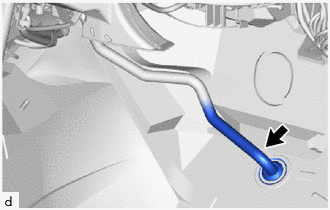
Disconnect the drain cooler hose.
-
-
REMOVE NO. 1 AIR DUCT
-
Detach the 3 claws and remove the No. 1 air duct.
Note
-
When removing, do not crack or deform the upper heater case of the air conditioning radiator assembly.
-
If the No. 1 air duct is reused, it may fall off or abnormal noise may occur. Therefore, make sure to replace with a new one.
-
-
-
REMOVE NO. 2 AIR DUCT
-
Detach the clamp.
-
Detach the 3 claws and remove the No. 2 air duct.
Note
-
When removing, do not crack or deform the upper heater case of the air conditioning radiator assembly.
-
If the No. 2 air duct is reused, it may fall off or abnormal noise may occur. Therefore, make sure to replace with a new one.
-
-
-
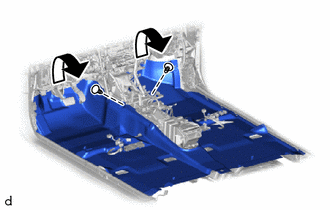
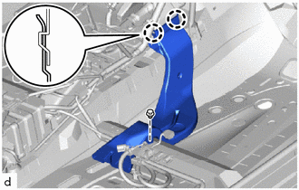
REMOVE NO. 1 INSTRUMENT PANEL BRACE SUB-ASSEMBLY
-
Detach the 4 clamps and disconnect the wire harness.
-
Remove the bolt, screw, 2 nuts and No. 1 instrument panel brace sub-assembly.
-
-
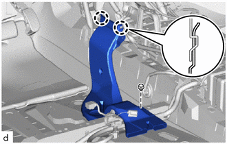
REMOVE NO. 2 INSTRUMENT PANEL BRACE SUB-ASSEMBLY
-
Detach the 3 clamps and disconnect the wire harness.
-
Remove the bolt and disconnect the ground wire.
-
Remove the bolt, screw, nut and No. 2 instrument panel brace sub-assembly.
-
-
REMOVE REAR NO. 1 AIR DUCT
-
Detach the 4 claws and remove the rear No. 1 air duct.
-
-
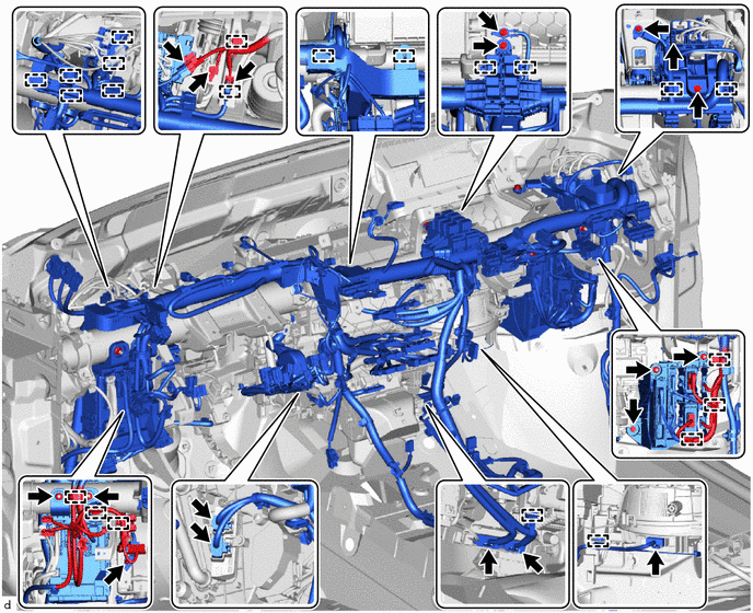
DISCONNECT INSTRUMENT PANEL WIRE
-
Remove the 3 bolts and disconnect the 3 ground wires.
-
Disconnect the connectors and detach the clamps.
-
Remove the 3 nuts and disconnect the instrument panel junction block assembly.
-
Remove the bolt and 2 nuts and disconnect the ECU integration box RH.
-
Remove the bolts and disconnect the instrument panel wire.
-
-
REMOVE AIR DUCT ASSEMBLY
-
Remove the 2 nuts and air duct assembly.
-
-
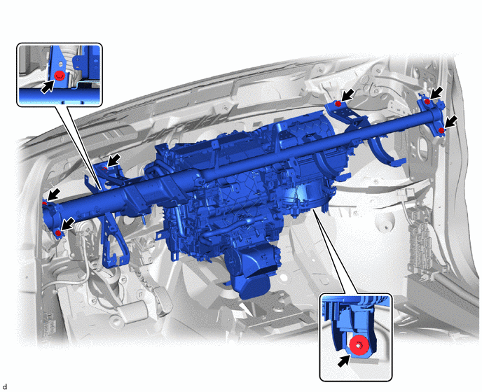
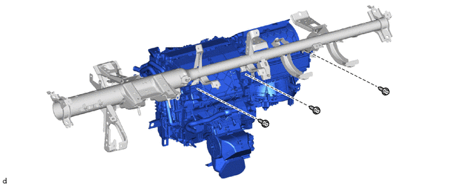
REMOVE INSTRUMENT PANEL REINFORCEMENT ASSEMBLY WITH AIR CONDITIONING UNIT ASSEMBLY
-
Remove the 7 bolts, nut and the instrument panel reinforcement assembly with air conditioning unit assembly.
-
-
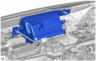
REMOVE AIR CONDITIONING UNIT ASSEMBLY
-
Remove the 3 bolts and the air conditioning unit assembly.
-