ELECTRONIC SHIFT LEVER SYSTEM(for V35A-FTS), Diagnostic DTC:P176C62, P271A11, P271A15, P271C11, P271C15
| DTC Code | DTC Name |
|---|---|
| P176C62 | Park Pawl Position Sensor "A"/"B" Signal Compare Failure |
| P271A11 | Park Pawl Position Sensor "A" Circuit Short to Ground |
| P271A15 | Park Pawl Position Sensor "A" Circuit Short to Battery or Open |
| P271C11 | Park Pawl Position Sensor "B" Circuit Short to Ground |
| P271C15 | Park Pawl Position Sensor "B" Circuit Short to Battery or Open |
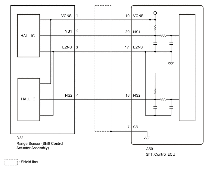
DESCRIPTION
The shift control actuator assembly has a built-in range sensor to detect the position of the parking lock actuator (in park (P) or not in park (P)). The range sensor is electrically controlled by a non-contact sensor (Hall IC).
| DTC No. | Detection Item | DTC Detection Condition | Trouble Area | MIL | Warning Indicate |
|---|---|---|---|---|---|
| P176C62 | Park Pawl Position Sensor "A"/"B" Signal Compare Failure | Range sensor pattern malfunction (mismatch in NS1 and NS2 judgment range) continuously occurs for 3 seconds or more |
|
Does not come on |
|
| P271A11 | Park Pawl Position Sensor "A" Circuit Short to Ground | The engine switch on (IG) and battery voltage is 10 V or higher, NS1 terminal voltage is below 0.35 V continuously for 1 second or more |
|
Does not come on |
|
| P271A15 | Park Pawl Position Sensor "A" Circuit Short to Battery or Open | The engine switch on (IG) and battery voltage is 10 V or higher, NS1 terminal voltage is higher than 4.65 V continuously for 1 second or more |
|
Does not come on |
|
| P271C11 | Park Pawl Position Sensor "B" Circuit Short to Ground | The engine switch on (IG) and battery voltage is 10 V or higher, NS2 terminal voltage is below 0.35 V continuously for 1 second or more |
|
Does not come on |
|
| P271C15 | Park Pawl Position Sensor "B" Circuit Short to Battery or Open | The engine switch on (IG) and battery voltage is 10 V or higher, NS2 terminal voltage is higher than 4.65 V continuously for 1 second or more |
|
Does not come on |
|
CONFIRMATION DRIVING PATTERN
Tech Tips
After repairs have been completed, clear the DTCs and then check that the vehicle has returned to normal by performing the All Readiness check procedure.
-
Turn the engine switch on (IG).
-
With the brake pedal depressed, move the shift lever to select neutral (N) and wait for 5 seconds or more.
-
Push the P position switch (shift position indicator) to select park (P) and wait for 5 seconds or more.
WIRING DIAGRAM
CAUTION / NOTICE / HINT
Note
-
After turning the engine switch off, waiting time may be required before disconnecting the cable from the negative (-) battery terminal. Therefore, make sure to read the disconnecting the cable from the negative (-) battery terminal notices before proceeding with work.
-
The vehicle is equipped with a sub-battery. Therefore, ensure there is no power being supplied to the vehicle when disconnecting or reconnecting the connector of the shift control ECU and when removing or installing the shift control ECU.
PROCEDURE
-
READ VALUE USING GTS (RANGE SENSOR VOLTAGE)
-
Connect the GTS to the DLC3.
-
Turn the engine switch on (IG).
-
Enter the following menus: Powertrain / Transmission / Data List / Park Pawl Position Sensor Voltage "A", Park Pawl Position Sensor Voltage "B".
Powertrain > Transmission > Data ListTester Display Park Pawl Position Sensor Voltage "A" Park Pawl Position Sensor Voltage "B" -
Depress the brake pedal and move the shift lever to select neutral (N).
-
Push the P position switch (shift position indicator) to select park (P).
-
Read the Data List according to the display on the GTS.
Result Data List Item Condition Specified Condition Park Pawl Position Sensor Voltage "A" Shift state park (P) (15 to 35°C (59 to 95°F)) 1.35 to 1.81 V Shift state neutral (N) (15 to 35°C (59 to 95°F)) 3.02 to 3.85 V Park Pawl Position Sensor Voltage "B" Shift state park (P) (15 to 35°C (59 to 95°F)) 3.02 to 3.85 V Shift state neutral (N) (15 to 35°C (59 to 95°F)) 1.35 to 1.81 V -
Turn the engine switch off.
Result Proceed to OK NG
OK 
CHECK FOR INTERMITTENT PROBLEMS Click here
NG 
-
-
CHECK HARNESS AND CONNECTOR (SHIFT CONTROL ECU - RANGE SENSOR (SHIFT CONTROL ACTUATOR ASSEMBLY))
-
Disconnect the A50 shift control ECU connector.
-
Disconnect the D32 range sensor (shift control actuator assembly) connector.
-
Measure the resistance according to the value(s) in the table below.
Standard Resistance (Check for Open) Tester Connection Condition Specified Condition A50-19 (VCNS) - D32-1 (VCNS) Always Below 1 Ω A50-20 (NS1) - D32-2 (NS1) Always Below 1 Ω A50-18 (NS2) - D32-4 (NS2) Always Below 1 Ω A50-17 (E2NS) - D32-3 (E2NS) Always Below 1 Ω Standard Resistance (Check for Short) Tester Connection Condition Specified Condition A50-19 (VCNS) or D32-1 (VCNS) - Body ground and other terminals Always 10 kΩ or higher A50-20 (NS1) or D32-2 (NS1) - Body ground and other terminals Always 10 kΩ or higher A50-18 (NS2) or D32-4 (NS2) - Body ground and other terminals Always 10 kΩ or higher A50-17 (E2NS) or D32-3 (E2NS) - Body ground and other terminals Always 10 kΩ or higher -
Reconnect the D32 range sensor (shift control actuator assembly) connector.
-
Reconnect the A50 shift control ECU connector.
Result Proceed to OK NG
NG
REPAIR OR REPLACE HARNESS OR CONNECTOR
OK
-
-
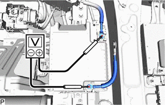
CHECK SHIFT CONTROL ECU (VCNS VOLTAGE)
-
Disconnect the D32 range sensor (shift control actuator assembly) connector.
-
Turn the engine switch on (IG).
-
Measure the voltage according to the value(s) in the table below.
Standard Voltage Tester Connection Switch Condition Specified Condition D32-1 (VCNS) - D32-3 (E2NS) Engine switch on (IG) 4.5 to 5.5 V Note
Turning the engine switch on (IG) with the connector disconnected causes other DTCs to be stored. Clear the DTCs after performing this inspection.
-
Turn the engine switch off.
-
Reconnect the D32 range sensor (shift control actuator assembly) connector.
Result Proceed to OK NG
NG
REPLACE SHIFT CONTROL ECU Click here
OK
-
-
CHECK SHIFT CONTROL ECU (NS1, NS2 VOLTAGE)
-
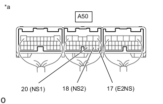
*a Component with harness connected
(Shift Control ECU)
Turn the engine switch on (IG).
-
Measure the voltage according to the value(s) in the table below.
Standard Voltage Tester Connection Condition Specified Condition A50-20 (NS1) - A50-17 (E2NS) Shift state park (P) 1.35 to 1.81 V Shift state neutral (N) 3.02 to 3.85 V A50-18 (NS2) - A50-17 (E2NS) Shift state park (P) 3.02 to 3.85 V Shift state neutral (N) 1.35 to 1.81 V -
Turn the engine switch off.
Result Proceed to OK NG
OK
REPLACE SHIFT CONTROL ECU Click here
NG
-
-
CHECK SHIFT CONTROL ECU (CHECK RESISTANCE)
-
Check that the voltage between the terminals of the sub-battery module assembly is 0 V.
-
Disconnect the cable from the negative (-) battery terminal.
-
Disconnect the D32 range sensor (shift control actuator assembly) connector.
-
Measure the resistance according to the value(s) in the table below.
Standard Resistance Tester Connection Condition Specified Condition D32-2 (NS1) - D32-1 (VCNS) 20°C (68°F) 180 to 220 kΩ D32-4 (NS2) - D32-1 (VCNS) 20°C (68°F) 180 to 220 kΩ -
Reconnect the D32 range sensor (shift control actuator assembly) connector.
-
Reconnect the cable to the negative (-) battery terminal.
Result Proceed to OK NG
OK
REPLACE SHIFT CONTROL ACTUATOR ASSEMBLY Click here
NG
REPLACE SHIFT CONTROL ECU Click here
-