REAR ACTIVE STABILIZER CONTROL ECU REMOVAL
CAUTION / NOTICE / HINT
The necessary procedures (adjustment, calibration, initialization, or registration) that must be performed after parts are removed, installed, or replaced during the absorber control ECU removal/installation are shown below.
| Replacement Part or Procedure | Necessary Procedure | Effect/Inoperative when not Performed | Link |
|---|---|---|---|
| Disconnect cable from negative battery terminal | Drive the vehicle until stop and start control is permitted (approximately 5 to 60 minutes) | Stop and start system | for 8GR-FKS: Click here for V35A-FTS: Click here |
| Memorize steering angle neutral point | LKA/LDA system | ||
| Parking support brake system* | |||
| Pre-collision system | |||
| Adaptive high beam system | |||
Lighting system (EXT) |
|||
| Variable gear ratio steering system | |||
| Parking assist monitor system | |||
| Panoramic view monitor system | |||
| Initialize rear door sunshade system | Rear door sunshade system | ||
| Initialize power trunk lid system | Power trunk lid system | ||
| Absorber Control ECU | Registration of Vehicle Identification Information |
|
Click here Click here
PROCEDURE
-
DISCONNECT CABLE FROM NEGATIVE BATTERY TERMINAL
Note
When disconnecting the cable, some systems need to be initialized after the cable is reconnected.
-
REMOVE BATTERY CARRIER CATCH BRACKET SUB-ASSEMBLY
-
REMOVE REAR ACTIVE STABILIZER CONTROL ECU
-
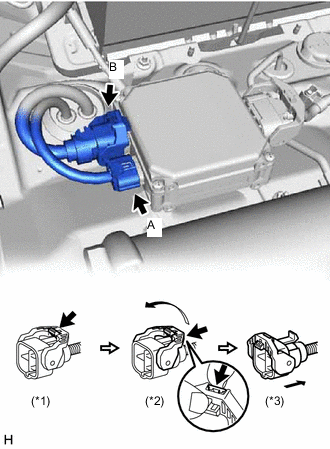
Disconnect the rear active stabilizer control actuator connector labeled A.
-
Disconnect the rear active stabilizer control actuator connector labeled B.
-
Release the lever's lock. (*1)
-
Press the claw and move the lever in the direction of the arrow in the illustration. (*2)
-
Disconnect the rear active stabilizer control actuator connector. (*3)
Note
When disconnecting the actuator connector, do not apply excessive force to the wire harness.
-
-
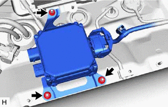
Remove the 3 nuts and rear active stabilizer control ECU.
-
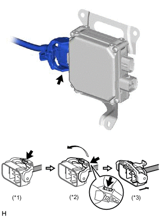
Disconnect the rear active stabilizer control ECU connector.
-
Release the lever's lock. (*1)
-
Press the claw and move the lever in the direction of the arrow in the illustration. (*2)
-
Disconnect the rear active stabilizer control ECU connector. (*3)
Note
When disconnecting the ECU connector, do not apply excessive force to the wire harness.
-
-
Disconnect the shielded ground wire connector.
-