INTEGRATION RELAY(for Engine Room Side) REMOVAL
CAUTION / NOTICE / HINT
The necessary procedures (adjustment, calibration, initialization, or registration) that must be performed after parts are removed, installed, or replaced during the No. 1 semiconductor power integration ECU removal/installation are shown below.
| Replaced Part or Performed Procedure | Necessary procedures | Effect/Inoperative Function when Necessary Procedure not Performed | Link |
|---|---|---|---|
| Disconnect cable from negative (-) battery terminal | Drive the vehicle until stop and start control is permitted (approximately 5 to 60 minutes) | Stop and start system | |
| Memorize steering angle neutral point | LKA/LDA system | ||
| Parking support brake system* | |||
| Pre-collision system | |||
| Adaptive high beam system | |||
Lighting system (EXT) |
|||
| Variable gear ratio steering system | |||
| Parking assist monitor system | |||
| Panoramic view monitor system | |||
| Initialize rear door sunshade system | Rear door sunshade system | ||
| Initialize power trunk lid system | Power trunk lid system |
Click here Click here
Tech Tips
-
Use the same procedure for RHD and LHD vehicles.
-
The procedure listed below is for LHD vehicles.
PROCEDURE
-
PRECAUTION
Note
After turning the engine switch off, waiting time may be required before disconnecting the cable from the negative (-) battery terminal. Therefore, make sure to read the disconnecting the cable from the negative (-) battery terminal notices before proceeding with work.
-
REMOVE LUGGAGE COMPARTMENT MAT SUB-ASSEMBLY
-
DISCONNECT CABLE FROM NEGATIVE BATTERY TERMINAL
-
REMOVE V-BANK COVER SUB-ASSEMBLY
-
REMOVE CENTER COWL TOP VENTILATOR LOUVER (for LHD)
-

Remove in this Direction Detach the clip and claw.
-
Detach the guide and remove the center cowl top ventilator louver.
-
-
REMOVE CENTER COWL TOP VENTILATOR LOUVER (for RHD)
-
Remove in this Direction Detach the clip and claw.
-
Detach the guide and remove the center cowl top ventilator louver.
-
-
REMOVE NO. 1 RELAY BLOCK COVER (for LHD)
-
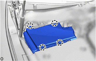
Detach the claw and remove the No. 1 relay block cover.
-
-
REMOVE NO. 1 RELAY BLOCK COVER (for RHD)
-
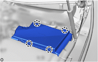
Detach the claw and remove the No. 1 relay block cover.
-
-
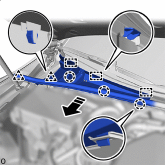
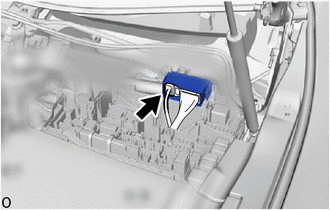
REMOVE NO. 1 SEMICONDUCTOR POWER INTEGRATION ECU (for LHD)
-
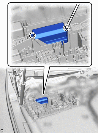

Protective Tape Using a thin-bladed screwdriver with its tip wrapped with protective tape, detach the claw and pull up the No. 1 semiconductor power integration ECU.
Note
-
Make sure the connector terminal is free from oil and grease.
-
Do not subject the No. 1 semiconductor power integration ECU to any impact.
-
Do not use a No. 1 semiconductor power integration ECU that has been dropped.
-
Do not disassemble the No. 1 semiconductor power integration ECU.
-
-
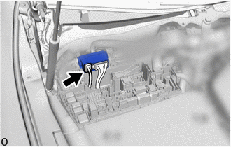
Disconnect the power source connector.
Note
-
Make sure the connector terminal is free from oil and grease.
-
Do not subject the No. 1 semiconductor power integration ECU to any impact.
-
Do not use a No. 1 semiconductor power integration ECU that has been dropped.
-
Do not disassemble the No. 1 semiconductor power integration ECU.
-
-
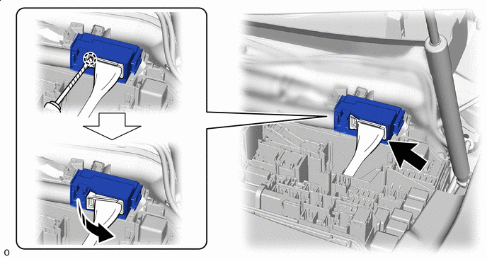
Using a thin-bladed screwdriver with its tip wrapped with protective tape, detach the claw and disconnect the lever connector.
Note
-
Make sure the connector terminal is free from oil and grease.
-
Do not subject the No. 1 semiconductor power integration ECU to any impact.
-
Do not use a No. 1 semiconductor power integration ECU that has been dropped.
-
Do not disassemble the No. 1 semiconductor power integration ECU.
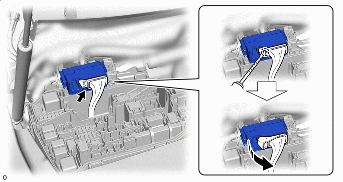
Rotate in this Direction Protective Tape -
-
-
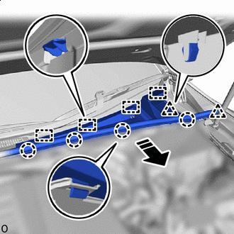
REMOVE NO. 1 SEMICONDUCTOR POWER INTEGRATION ECU (for RHD)
-
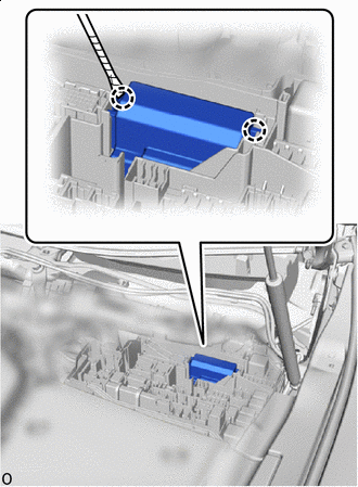
Protective Tape Using a thin-bladed screwdriver with its tip wrapped with protective tape, detach the claw and pull up the No. 1 semiconductor power integration ECU.
Note
-
Make sure the connector terminal is free from oil and grease.
-
Do not subject the No. 1 semiconductor power integration ECU to any impact.
-
Do not use a No. 1 semiconductor power integration ECU that has been dropped.
-
Do not disassemble the No. 1 semiconductor power integration ECU.
-
-
Disconnect the power source connector.
Note
-
Make sure the connector terminal is free from oil and grease.
-
Do not subject the No. 1 semiconductor power integration ECU to any impact.
-
Do not use a No. 1 semiconductor power integration ECU that has been dropped.
-
Do not disassemble the No. 1 semiconductor power integration ECU.
-
-
Using a thin-bladed screwdriver with its tip wrapped with protective tape, detach the claw and disconnect the lever connector.
Note
-
Make sure the connector terminal is free from oil and grease.
-
Do not subject the No. 1 semiconductor power integration ECU to any impact.
-
Do not use a No. 1 semiconductor power integration ECU that has been dropped.
-
Do not disassemble the No. 1 semiconductor power integration ECU.
Rotate in this Direction Protective Tape -
-