FUEL PUMP INSTALLATION

PROCEDURE
-
INSTALL FUEL SUCTION TUBE WITH PUMP AND GAUGE ASSEMBLY
-
Install a new fuel suction tube set gasket to the fuel tank assembly.
-
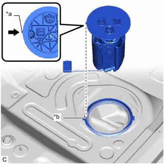
*a Protrusion *b Notch Set the fuel suction tube with pump and gauge assembly to the fuel tank assembly.
Note
Be careful not to bend the arm of the fuel sender gauge assembly.
Tech Tips
Align the protrusion of the fuel suction tube with pump and gauge assembly with the notch of the tank suction tube support.
-
-
INSTALL FUEL PUMP GAUGE RETAINER
-
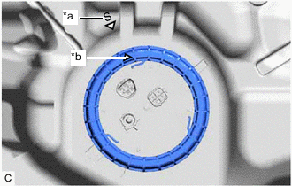
*a "S" Mark *b Triangle Mark Align the triangle mark on new fuel pump gauge retainer with the "S" mark on the fuel tank assembly while pushing down the fuel suction tube with pump and gauge assembly, attach the fuel pump gauge retainer.
-
Install SST (fuel pump retainer tool assy) to the fuel pump gauge retainer.
-
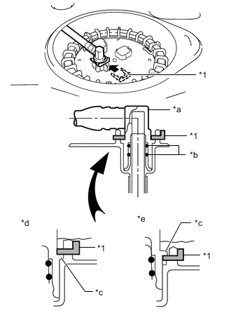
Insert 2 SST (claw) between the service hole and fuel pump gauge retainer, and adjust the position so that the protrusions of the fuel pump gauge retainer are aligned with the grooves of SST (claw) as shown in the illustration.
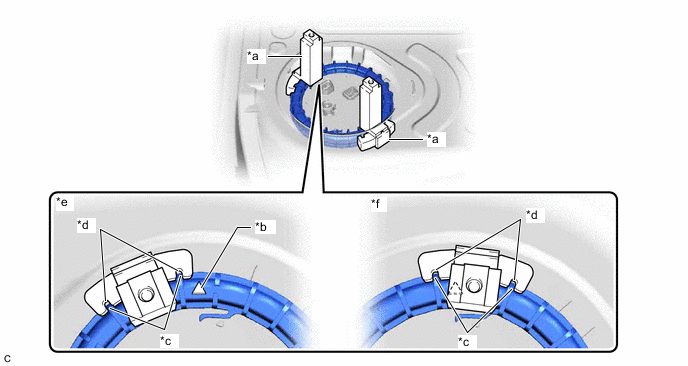
*a SST (Claw) *b Triangle Mark *c Protrusion of Fuel Pump Gauge Retainer *d Groove of SST (Claw) *e Correct *f Incorrect - SST
- 09808-14040 ( 09882-14040 )
Note
Ensure that SST (claw) does not cover the triangle mark of the fuel pump gauge retainer.
-
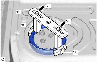
*a SST (Claw) *b SST (Plate) *c SST (Bolt and Washer Set) While ensuring that SST (plate) is centered, install SST (plate) to 2 SST (claw) with 2 SST (bolt and washer set).
- SST
- 09808-14040 ( 09881-14040, 09883-14040 )
-
-
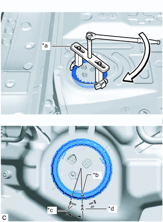
*a SST (Fuel Pump Retainer Tool Assy) *b Triangle Mark *c "MAX" Mark *d "A" Mark While lightly pushing down on SST (fuel pump retainer tool assy), tighten the fuel pump gauge retainer by 1 and a half turns so that the triangle mark on the fuel pump gauge retainer is positioned between the "MAX" and "A" marks on the fuel tank assembly.
Note
-
Do not use any tools other than specified as this may result in damage to the fuel pump gauge retainer or fuel tank assembly.
-
Do not push down on SST (fuel pump retainer tool assy) excessively as this may make the fuel pump gauge retainer hard to rotate, and may damage components.
-
Make sure to turn the breaker bar horizontally. If it is turned at an angle, SST (fuel pump retainer tool assy) may come off.
-
Do not spin SST (fuel pump retainer tool assy) too fast or use an impact wrench as this may damage components.
-
If SST (fuel pump retainer tool assy) comes off of the fuel pump gauge retainer, loosen SST (bolt and washer set) and reinstall SST (fuel pump retainer tool assy).
Tech Tips
While pushing down on SST (fuel pump retainer tool assy), turn the fuel pump gauge retainer clockwise to tighten. Make sure that the detent of the tank suction tube support does not move out of the groove of the fuel tank assembly.
-
-
-
CONNECT FUEL TANK MAIN TUBE SUB-ASSEMBLY
-
*1 Tube Joint Clip *a Fuel Tube Joint *b O-ring *c Collar *d Correct *e Incorrect Push the fuel tube joint onto the plug of the fuel suction plate sub-assembly, then install the tube joint clip.
Note
-
Check that there are no scratches or foreign matter around the connecting parts of the fuel tube joint and plug before performing this work.
-
Check that the fuel tube joint is securely inserted to the end.
-
Check that the tube joint clip is on the collar of the fuel tube joint.
-
After installing the tube joint clip, check that the fuel tank main tube sub-assembly is securely connected by pulling on it.
-
-
-
CHECK AIRTIGHTNESS
-
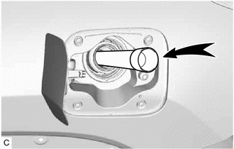
After installing the fuel suction tube with pump and gauge assembly, check for fuel leaks by first applying soapy water to the area where the fuel suction plate sub-assembly and fuel pump gauge retainer contact, and then blow forcibly into the fuel inlet area through a flexible pouring spout or similar tube.
-
Blow forcibly until the reverse flow prevention valve inside the fuel inlet activates.
Note
Be careful not to inhale any fuel vapor.
Tech Tips
There should be a faintly audible sound when the reverse flow prevention valve operates.
-
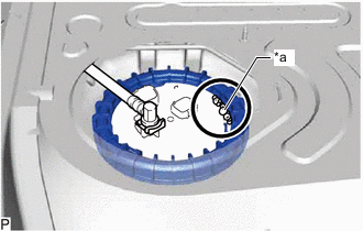
*a Air Bubbles Check that the contact areas of the fuel suction tube with pump and gauge assembly, etc. has resulted in a condition where fuel will leak, air will leak out as shown in the illustration.
Note
If air leaks out, recheck the installation condition, and replace the fuel pump gauge retainer and fuel suction tube set gasket with new ones. Also, make sure to fully wipe away the soapy water. (Any remaining soapy water can cause the fuel suction tube set gasket to slip and result in an improper seal.)
-
-
INSTALL REAR FLOOR SERVICE HOLE COVER
-
Remove any remaining butyl tape from the rear floor service hole cover and vehicle body.
-
Clean the installation surfaces of the rear floor service hole cover and vehicle body.
-
Connect the 2 fuel pump connectors.
-
Install the rear floor service hole cover with new butyl tape.
-
w/ Rear No. 2 Seat:
-
Return the rear No. 2 floor silencer to its original position.
-
Return the rear floor silencer to its original position.
-
Install the rear No. 1 floor silencer pad and No. 2 floor silencer pad to the vehicle body with the 2 No. 3 dash panel insulator plates.
-
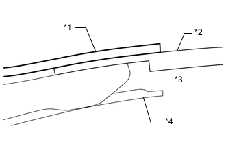
*1 Front Floor Carpet Assembly *2 Rear Floor Carpet Assembly *3 No. 1 Floor Silencer Pad and No. 2 Floor Silencer Pad *4 Rear Floor Silencer Return the front floor carpet assembly to its original position as shown in the illustration.
-
-
w/o Rear No. 2 Seat:
-
Return the rear floor silencer to its original position.
-
Return the front floor carpet assembly to its original position and install the 3 clips.
-
-
-
CONNECT CABLE TO NEGATIVE BATTERY TERMINAL
Note
When disconnecting the cable, some systems need to be initialized after the cable is reconnected.
-
INSPECT FOR FUEL LEAK
-
INSTALL REAR SEAT SIDE GARNISH LH
-
w/ Rear No. 2 Seat:
-
w/o Rear No. 2 Seat:
-
-
INSTALL FRONT DECK SIDE TRIM COVER LH (w/ Rear No. 2 Seat)
-
INSTALL UPPER QUARTER TRIM PAD LH (w/o Rear No. 2 Seat)
-
INSTALL REAR SEAT SIDE GARNISH RH
Tech Tips
Use the same procedure as for the LH side.
-
INSTALL FRONT DECK SIDE TRIM COVER RH (w/ Rear No. 2 Seat)
Tech Tips
Use the same procedure as for the LH side.
-
INSTALL UPPER QUARTER TRIM PAD RH (w/o Rear No. 2 Seat)
Tech Tips
Use the same procedure as for the LH side.
-
INSTALL REAR SEAT ASSEMBLY LH (w/o Rear No. 2 Seat)
-
INSTALL REAR SEAT ASSEMBLY RH (w/o Rear No. 2 Seat)
-
INSTALL REAR NO. 1 SEAT ASSEMBLY (w/ Rear No. 2 Seat)
-
for 60/40 Split Seat Type LH Side:
-
for 60/40 Split Seat Type RH Side:
-
-
INSTALL REAR DOOR SCUFF PLATE LH
-
w/ Rear No. 2 Seat:
-
w/o Rear No. 2 Seat:
-
-
INSTALL REAR DOOR INSIDE SCUFF PLATE LH (w/ Rear No. 2 Seat)
-
INSTALL REAR DOOR SCUFF PLATE RH
Tech Tips
Use the same procedure as for the LH side.
-
INSTALL REAR DOOR INSIDE SCUFF PLATE RH (w/ Rear No. 2 Seat)
Tech Tips
Use the same procedure as for the LH side.
-
INSTALL REAR NO. 2 SEAT ASSEMBLY (w/ Rear No. 2 Seat)
-
PERFORM INITIALIZATION
-
Perform "Inspection After Repair" after replacing the fuel pump.
-
w/ Canister Pump Module:
-
w/o Canister Pump Module:
-
-