RADIO ANTENNA CORD INSTALLATION
PROCEDURE
-
INSTALL NO. 4 ANTENNA CORD SUB-ASSEMBLY (w/ FM Sub-antenna)
-
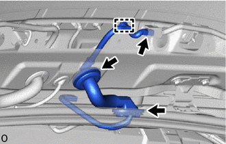
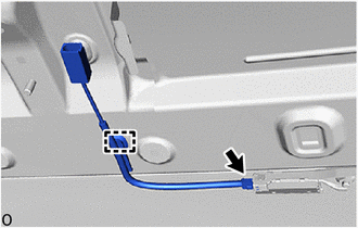
Engage the clamp and 2 grommets to install the No. 4 antenna cord sub-assembly.
-
Connect the connector.
-
-
INSTALL BACK DOOR TRIM UPPER PANEL ASSEMBLY (w/ FM Sub-antenna)
-
INSTALL NO. 3 ANTENNA CORD SUB-ASSEMBLY
-
w/o FM Sub-antenna:
-
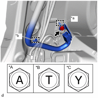
*A for Type A *B for Type B *C for Type C *a Guide *b Clamp Engage the clamp and guide to temporarily install the No. 3 antenna cord sub-assembly.
-
Install the bolt.
- Torque:
- for Type A
- 10.5 N*m { 107 kgf*cm, 8 ft.*lbf }
- for Type B
- 10 N*m { 102 kgf*cm, 7 ft.*lbf }
- for Type C
- 10 N*m { 102 kgf*cm, 7 ft.*lbf }
-
Engage the clamps install the No. 3 antenna cord sub-assembly.
-
Connect the connector.
-
-
w/ FM Sub-antenna:
-
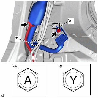
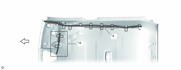
*A for Type A *B for Type B *a Guide *b Clamp Engage the clamp and guide to temporarily install the No. 3 antenna cord sub-assembly.
-
Install the bolt.
- Torque:
- for Type A
- 10.5 N*m { 107 kgf*cm, 8 ft.*lbf }
- for Type B
- 10 N*m { 102 kgf*cm, 7 ft.*lbf }
-
Connect the connector of the floor wire.
-
Engage the clamps install the No. 3 antenna cord sub-assembly.
-
Connect the connector.
-
Connect the connector of the No. 4 antenna cord sub-assembly.
-
-
-
INSTALL NO. 5 ANTENNA CORD SUB-ASSEMBLY (w/ Digital Audio Broadcasting Antenna)
-
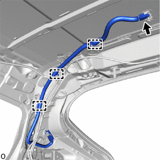
Engage the clamp to install the No. 5 antenna cord sub-assembly.
-
Connect the connector.
-
-
INSTALL NO. 2 ANTENNA CORD SUB-ASSEMBLY
-
Type A:
-
Remove the old double-sided tape from the roof headlining.
*A w/ Digital Audio Broadcasting Antenna - - *a Marking - - 
Double-sided Tape 
Front -
Prepare an appropriate amount of new double-sided tape.
Tech Tips
Be careful not to touch the adhesive surface.
-
Apply the double-sided tape to the roof headlining while aligning the tape with the markings on the roof headlining.
-
Peel off the release paper from the double-sided tape.
-
Engage the No. 2 antenna cord sub-assembly to the notch of the roof headlining.
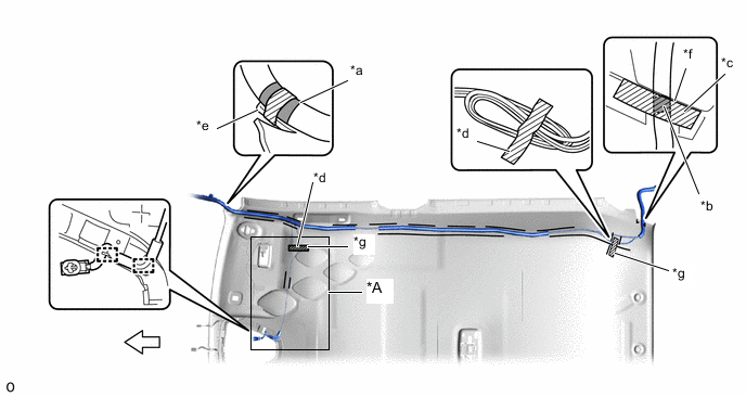
*A w/ Digital Audio Broadcasting Antenna - - *a Marking Tape (A) *b Marking Tape (B) *c Adhesive Tape (A) *d Adhesive Tape (B) *e Protrusion *f Edge of the roof headlining *g Adjustment Area - - Front - - -
Engage the clamp.
-
Align the marking tape (A) on the No. 2 antenna cord sub-assembly with the protrusion on the front of the roof headlining and wrap tape around the No. 2 antenna cord sub-assembly and protrusion of the roof headlining.
-
Install the No. 2 antenna cord sub-assembly on the double-sided tape of the roof headlining.
Note
-
Make sure that there are no gaps between the roof headlining and No. 2 antenna cord sub-assembly, and that the No. 2 antenna cord sub-assembly is not twisted.
-
Make sure the No. 2 antenna cord assembly is securely installed. If any part of the No. 2 antenna cord sub-assembly is loose, it will cause an abnormal noise.
-
-
Align the marking tape (B) on the No. 2 antenna cord sub-assembly with the edge of roof headlining on the roof headlining and secure the No. 2 antenna cord sub-assembly with the adhesive tape (A) as shown in the illustration.
Note
Make sure that there are no gaps between the roof headlining and No. 2 antenna cord sub-assembly, and that the No. 2 antenna cord sub-assembly is not twisted.
-
Apply the 2 adhesive tapes (B) as shown in the illustration to secure the No. 2 antenna cord subassembly.
Tech Tips
Secure the extra length of the No. 2 antenna cord sub-assembly in the adjustment area as shown in the illustration.
-
-
Type B:
-
Engage the No. 2 antenna cord sub-assembly to the notch of the roof headlining.
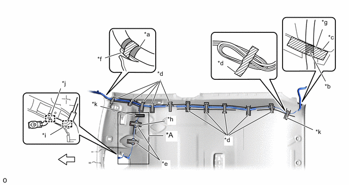
*A w/ Digital Audio Broadcasting Antenna - - *a Marking Tape (A) *b Marking Tape (B) *c Adhesive Tape (A) *d Adhesive Tape (B) *e Adhesive Tape (C) *f Protrusion *g Edge of the roof headlining *h Marking (B) *i Clamp *j Notch *k Adjustment Area - - Front - - -
Engage the clamp.
-
Align the marking tape (A) on the No. 2 antenna cord sub-assembly with the protrusion on the front of the roof headlining and wrap tape around the No. 2 antenna cord sub-assembly and protrusion of the roof headlining.
-
Install the No. 2 antenna cord sub-assembly on the butyl tape of the roof headlining.
Note
-
Make sure that there are no gaps between the roof headlining and No. 2 antenna cord sub-assembly, and that the No. 2 antenna cord sub-assembly is not twisted.
-
Make sure the No. 2 antenna cord assembly is securely installed. If any part of the No. 2 antenna cord sub-assembly is loose, it will cause an abnormal noise.
-
-
Install the No. 2 antenna cord sub-assembly on the butyl tape of the roof headlining from the clamp to the marking (B).
Note
-
Make sure that there are no gaps between the roof headlining and No. 2 antenna cord sub-assembly, and that the No. 2 antenna cord sub-assembly is not twisted.
-
Make sure the No. 2 antenna cord assembly is securely installed. If any part of the No. 2 antenna cord sub-assembly is loose, it will cause an abnormal noise.
-
-
Align the marking tape (B) on the No. 2 antenna cord sub-assembly with the edge of roof headlining on the roof headlining and secure the No. 2 antenna cord sub-assembly with the adhesive tape (A) as shown in the illustration.
Note
Make sure that there are no gaps between the roof headlining and No. 2 antenna cord sub-assembly, and that the No. 2 antenna cord sub-assembly is not twisted.
-
Apply the 11 adhesive tapes (B) as shown in the illustration to secure the No. 2 antenna cord subassembly.
Tech Tips
Secure the extra length of the No. 2 antenna cord sub-assembly in the adjustment area as shown in the illustration.
-
Apply the 2 adhesive tapes (C) as shown in the illustration to secure the No. 2 antenna cord subassembly.
Tech Tips
Secure the extra length of the No. 2 antenna cord sub-assembly in the adjustment area as shown in the illustration.
-
-
-
INSTALL ROOF HEADLINING
-
INSTALL ANTENNA CORD SUB-ASSEMBLY (for LHD)
-
Engage the clamps to install the antenna cord sub-assembly.
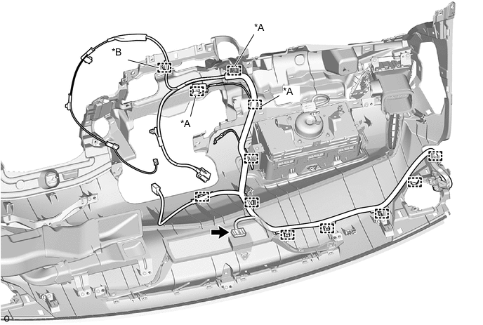
*A w/ USB Audio System *B w/ Manual (SOS) Switch -
w/ Manual (SOS) Switch:
-
Connect the connector.
-
-
-
INSTALL ANTENNA CORD SUB-ASSEMBLY (for RHD)
-
Engage the clamps to install the antenna cord sub-assembly.
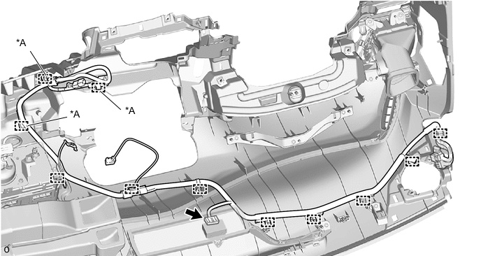
*A w/ USB Audio System - - -
w/ Navigation System:
-
Connect the connector.
-
-
-
INSTALL NO. 3 HEATER TO REGISTER DUCT SUB-ASSEMBLY (for LHD)
-
INSTALL NO. 1 HEATER TO REGISTER DUCT SUB-ASSEMBLY (for RHD)
-
INSTALL INSTRUMENT PANEL SAFETY PAD