VEHICLE STABILITY CONTROL SYSTEM Brake Warning Light Remains ON
DESCRIPTION
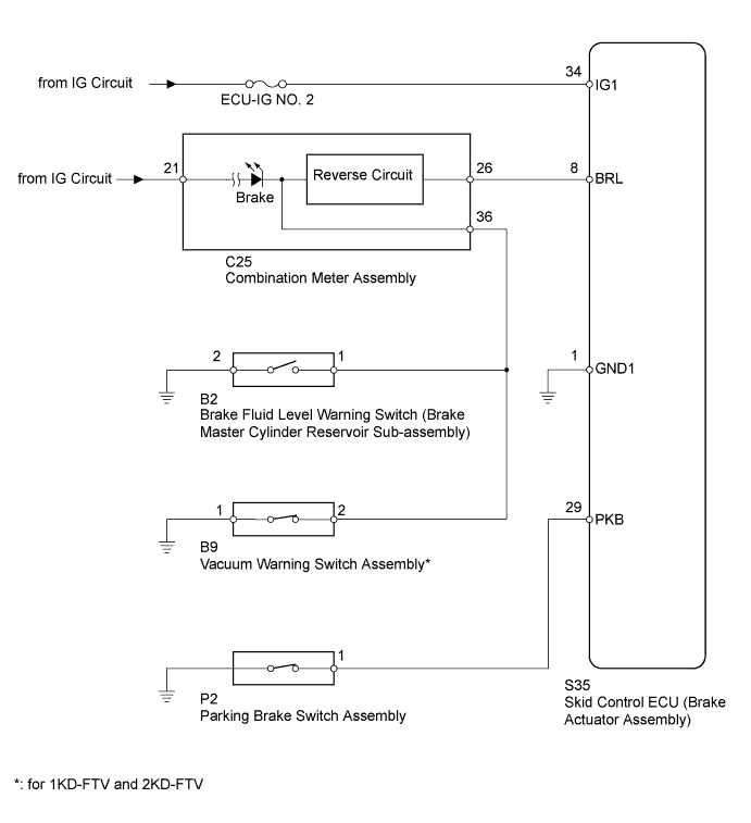
When one of the following conditions is met, the brake warning light remains on:
-
The skid control ECU (brake actuator assembly) connector is disconnected from the skid control ECU (brake actuator assembly).
-
The brake fluid level is insufficient.
-
The parking brake is applied.
-
The vacuum inside the brake booster decreases.
-
There is an open circuit in the harness between the combination meter and the skid control ECU (brake actuator assembly).
-
EBD operation has been disabled.
WIRING DIAGRAM
INSPECTION PROCEDURE
Note
-
After replacing the brake actuator assembly, perform calibration Click here.
-
Inspect the fuses for circuits related to this system before performing the following inspection procedure.
-
Before disconnecting the connector, make sure that there are no problems with the connection.
-
After disconnecting the connector, make sure that the connector case and terminals are not deformed or corroded.
PROCEDURE
-
CHECK FOR DTC
-
Check for DTCs Click here.
Result Result Proceed to DTC is not output A DTC is output B
B 
REPAIR CIRCUITS INDICATED BY OUTPUT DTCS Click here
A 
-
-
CHECK IF SKID CONTROL ECU CONNECTOR IS SECURELY CONNECTED
-
Check if the skid control ECU (brake actuator assembly) connector is securely connected.
OK The connector is securely connected.
NG
CONNECT CONNECTOR TO ECU CORRECTLY
OK
-
-
CHECK TERMINAL VOLTAGE (IG1 TERMINAL)
-
Turn the ignition switch off.
-
Disconnect the skid control ECU (brake actuator assembly) connector.
-
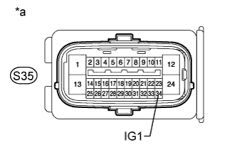
Text in Illustration *a Front view of wire harness connector
(to Skid Control ECU [Brake Actuator Assembly])
Measure the voltage according to the value(s) in the table below.
Standard Voltage Tester Connection Switch Condition Specified Condition S35-34 (IG1) - Body ground Ignition switch ON 11 to 14 V
NG
REPAIR OR REPLACE HARNESS OR CONNECTOR
OK
-
-
CHECK HARNESS AND CONNECTOR (GND1 TERMINAL)
-
Turn the ignition switch off.
-
Disconnect the skid control ECU (brake actuator assembly) connector.
-
Measure the resistance according to the value(s) in the table below.
Standard Resistance Tester Connection Condition Specified Condition S35-1 (GND1) - Body ground Always Below 1 Ω
NG
REPAIR OR REPLACE HARNESS OR CONNECTOR
OK
-
-
CHECK BRAKE BOOSTER ASSEMBLY
-
Check the brake booster assembly Click here.
NG
REPLACE BRAKE BOOSTER ASSEMBLY Click here
OK
-
-
INSPECT BRAKE FLUID LEVEL WARNING SWITCH
-
Turn the ignition switch to ON.
-
With the brake fluid at the specified level, disconnect the brake fluid level warning switch (brake master cylinder reservoir sub-assembly) connector and check the brake warning light.
Result Result Proceed to Brake warning light turns off A Brake warning light does not turn off for 1KD-FTV and 2KD-FTV B except for 1KD-FTV and 2KD-FTV C Tech Tips
If the brake warning light turns off, the brake fluid level warning switch (brake master cylinder reservoir sub-assembly) has an internal short circuit.
B 
CHECK VACUUM WARNING SWITCH ASSEMBLY Click here
C
INSPECT PARKING BRAKE SWITCH ASSEMBLY Click here
A 
REPLACE BRAKE MASTER CYLINDER RESERVOIR SUB-ASSEMBLY Click here
-
-
CHECK VACUUM WARNING SWITCH ASSEMBLY
-
Start the engine.
-
Idle the engine.
-
Disconnect the vacuum warning switch connector and check the brake warning light.
Result Result Proceed to Brake warning light does not turn off A Brake warning light turns off B Tech Tips
If the brake warning light turns off, the vacuum warning switch has an internal short circuit.
B
REPLACE VACUUM WARNING SWITCH ASSEMBLY Click here
A
-
-
INSPECT PARKING BRAKE SWITCH ASSEMBLY
-
Turn the ignition switch off.
-
Remove the parking brake switch.
-
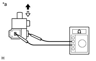
Text in Illustration *a Component without harness connected
(Parking Brake Switch Assembly)

On 
Off Measure the resistance according to the value(s) in the table below.
Standard Resistance Tester Connection Switch Condition Specified Condition Switch connector terminal - Switch body On (Shaft is not pressed) Below 1 Ω Off (Shaft is pressed) 10 kΩ or higher
NG
REPLACE PARKING BRAKE SWITCH ASSEMBLY
OK
-
-
CHECK HARNESS AND CONNECTOR (SKID CONTROL ECU - COMBINATION METER AND PARKING BRAKE SWITCH)
-
Turn the ignition switch off.
-
Disconnect the skid control ECU (brake actuator assembly) connector.
-
Disconnect the C25 combination meter connector.
-
Disconnect the parking brake switch connector.
-
Measure the resistance according to the value(s) in the table below.
Standard Resistance Tester Connection Condition Specified Condition S35-8 (BRL) - C25-26 Always Below 1 Ω S35-8 (BRL) - Body ground Always 10 kΩ or higher S35-29 (PKB) - P2-1 Always Below 1 Ω S35-29 (PKB) - Body ground Always 10 kΩ or higher
NG
REPAIR OR REPLACE HARNESS OR CONNECTOR
OK
-
-
CHECK HARNESS AND CONNECTOR (COMBINATION METER - BODY GROUND)
-
Turn the ignition switch off.
-
Disconnect the C25 combination meter connector.
-
Disconnect the skid control ECU (brake actuator assembly) connector.
-
Disconnect the brake fluid level warning switch (brake master cylinder reservoir assembly) connector.
-
Disconnect the vacuum warning switch connector.
-
Measure the resistance according to the value(s) in the table below.
Standard Resistance Tester Connection Condition Specified Condition C25-36 - Body ground Always 10 kΩ or higher
NG
REPAIR OR REPLACE HARNESS OR CONNECTOR
OK
-
-
PERFORM ACTIVE TEST USING INTELLIGENT TESTER (BRAKE WARNING LIGHT)
-
Turn the ignition switch off.
-
Connect the intelligent tester to the DLC3.
-
Turn the ignition switch to ON.
-
Turn the intelligent tester on.
-
Enter the following menus: Chassis / ABS/VSC/TRC / Active Test.
ABS/VSC/TRC Tester Display Test Part Control Range Diagnostic Note Brake Warning Light Brake warning light Warning light ON / OFF Observe the combination meter. -
When performing the Brake Warning Light Active Test, check Brake Warning Light in the Data List.
ABS/VSC/TRC Tester Display Measurement Item / Range Normal Condition Diagnostic Note Brake Warning Light Brake warning light /
ON or OFF
ON: Brake warning light on
OFF: Brake warning light off
- Result Result Proceed to Data List Display Data List Display When Performing Active Test ON/OFF Operation ON Does not change between ON and OFF for LHD A Does not change between ON and OFF for RHD B Changes between ON and OFF C OFF Does not change between ON and OFF for LHD A Does not change between ON and OFF for RHD B Changes between ON and OFF C
B
REPLACE BRAKE ACTUATOR ASSEMBLY Click here
C
GO TO METER / GAUGE SYSTEM (HOW TO PROCEED WITH TROUBLESHOOTING) Click here
A
REPLACE BRAKE ACTUATOR ASSEMBLY Click here
-