ECD SYSTEM, Diagnostic DTC:P1520
| DTC Code | DTC Name |
|---|---|
| P1520 | Stop Light Switch Circuit |
DESCRIPTION
In this system, the signal of the stop light switch is used to judge whether the stop light system is abnormal or not.
The stop light switch has a duplex system (signals STP and ST1-) to memorize the abnormality when the signals of depressing and releasing the brake pedal are detected simultaneously.
Tech Tips
Normal condition is as shown in the table.
| Signal | Brake pedal released | In transition | Brake pedal depressed |
|---|---|---|---|
| STP | OFF | ON | ON |
| ST1- | ON | ON | OFF |
| DTC No. | DTC Detection Condition | Trouble Area |
|---|---|---|
| P1520 | When STP (without depressing the brake pedal) and ST1- (with the brake pedal depressed) signals continue for longer than 0.5 seconds with the ignition switch ON. |
|
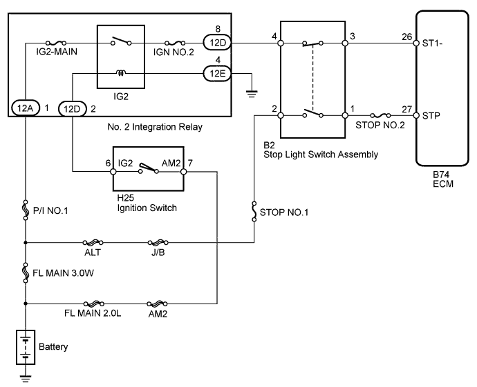
WIRING DIAGRAM
INSPECTION PROCEDURE
Note
Inspect the fuses for circuits related to this system before performing the following inspection procedure.
Tech Tips
Read freeze frame data using the GTS. Freeze frame data records the engine condition when malfunctions are detected. When troubleshooting, freeze frame data can help determine if the vehicle was moving or stationary, if the engine was warmed up or not, and other data from the time the malfunction occurred.
PROCEDURE
-
CHECK STOP LAMP SWITCH ASSEMBLY (TERMINAL B VOLTAGE)
-
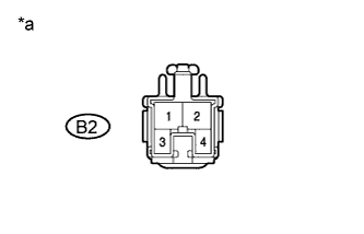
Text in Illustration *a Front view of wire harness connector
(to Stop Light Switch Assembly)
Disconnect the stop light switch assembly connector.
-
Measure the voltage according to the value(s) in the table below.
Standard Voltage Tester Connection Condition Specified Condition B2-2 - Body ground Always 11 to 14 V B2-4 - Body ground Ignition switch ON 11 to 14 V
NG 
REPAIR OR REPLACE HARNESS OR CONNECTOR
OK 
-
-
INSPECT STOP LAMP SWITCH ASSEMBLY
-
Disconnect the stop light switch assembly connector.
-
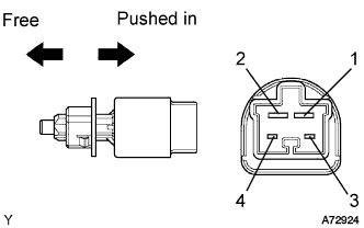
Check the resistance between each pair of the terminals.
Standard Resistance Switch Position Tester Connection Specified Condition Switch pin free 1 - 2 Below 1 Ω Switch pin pushed in 1 - 2 10 kΩ or higher Switch pin free 3 - 4 10 kΩ or higher Switch pin pushed in 3 - 4 Below 1 Ω
NG
REPLACE STOP LAMP SWITCH ASSEMBLY
OK
-
-
INSPECT ECM (STP AND ST1- VOLTAGE)
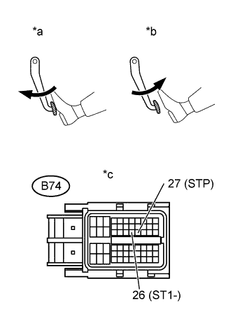
Text in Illustration *a Brake Pedal Depressed *b Brake Pedal Released *c Front view of wire harness connector
(to ECM)
-
Disconnect the ECM connector.
-
Turn the ignition switch to ON.
-
Measure the voltage according to the value(s) in the table below.
Standard Voltage Tester Connection Brake Pedal Condition Specified Condition B74-26 (ST1-) - Body ground Released 11 to 14 V Depressed Below 1.5 V B74-27 (STP) - Body ground Released Below 1.5 V Depressed 11 to 14 V
NG
REPAIR OR REPLACE HARNESS OR CONNECTOR
OK 
REPLACE ECM Click here
-