ECD SYSTEM Pre-heating Control Circuit
DESCRIPTION
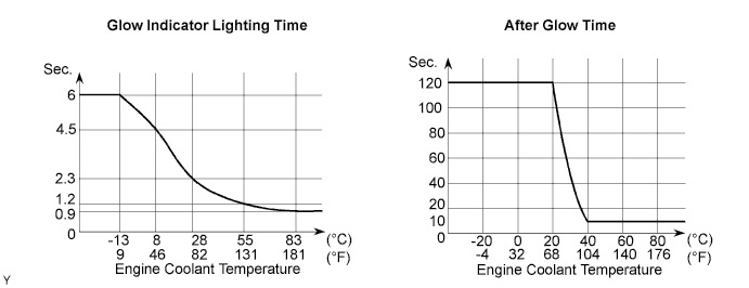
When the ignition switch turns ON, the ECM calculates the glow indicator lighting time/heating corresponding to the coolant temperature at that time and turns on the glow indicator light/GLOW relay.
As the ceramics is used for a glow plug material, the current control is not performed.
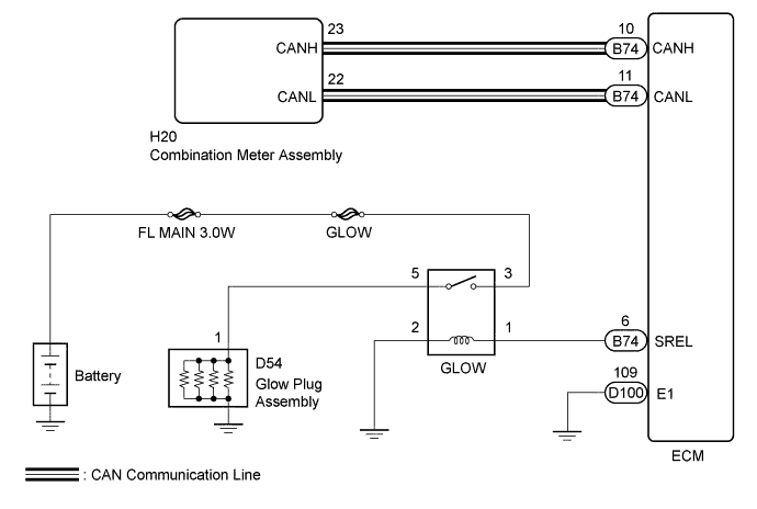
WIRING DIAGRAM
INSPECTION PROCEDURE
Note
Inspect the fuses for circuits related to this system before performing the following inspection procedure.
PROCEDURE
-
CHECK GLOW INDICATOR LIGHT
-
Turn the ignition switch to ON.
-
Check that the glow indicator light comes on.
OK The glow indicator light remains on for 0.5 second or more and then goes off.
OK 
INSPECT GLOW PLUG ASSEMBLY (INSTALLATION) Click here
NG
CHECK WHETHER DTC OUTPUT RECURS Click here
-
-
CHECK WHETHER DTC OUTPUT RECURS
-
Connect the GTS to the DLC3.
-
Turn the ignition switch to ON.
-
Turn the GTS on.
-
Enter the following menus: System Select / Health Check.
-
Check the DTCs.
Result Result Proceed to DTC is not output A Any DTC is output B
B 
GO TO RELEVANT DTC CHART
A 
-
-
PERFORM ACTIVE TEST USING GTS
-
Connect the GTS to the DLC3.
-
Turn the ignition switch to ON.
-
Turn the GTS on.
-
Enter the following menus: Body Electrical / Combination Meter / Active Test / Indicat GLOW.
-
Check the status of the MIL while performing the Active Test.
Result Result Proceed to Changes A Does not change B
B
REPLACE COMBINATION METER ASSEMBLY Click here
A
-
-
INSPECT GLOW PLUG ASSEMBLY (INSTALLATION)
-
Check that the glow plug and glow plug wire are securely installed.
OK The glow plug and glow plug wire are securely installed.
NG
TIGHTEN GLOW PLUG ASSEMBLY
OK
-
-
INSPECT GLOW PLUG ASSEMBLY
-
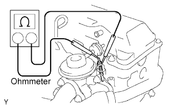
Measure the resistance according to the value(s) in the table below.
Standard resistance 0.72 Ω at 20°C (68°F) Tech Tips
The higher the atmospheric temperature is the larger the resistance becomes and vice versa.
NG
REPLACE GLOW PLUG ASSEMBLY
OK
-
-
CHECK FOR INDICATOR LIGHTING TIME AND AFTER GLOW TIME
-
Check for indicator lighting time and after glow time Click here.
NG
REPLACE ECM Click here
OK
-
-
INSPECT GLOW RELAY
-
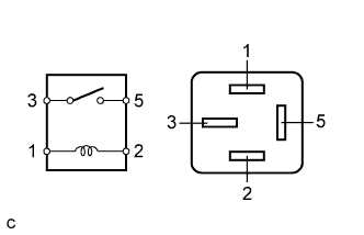
Measure the resistance according to the value(s) in the table below.
Standard Resistance Tester Connection Specified Condition 3 - 5 10 kΩ or higher 3 - 5 Below 1 Ω
(When battery voltage is applied to terminals 1 and 2)
NG
REPLACE GLOW RELAY
OK
-
-
CHECK HARNESS AND CONNECTOR (ECM - GLOW RELAY, GLOW RELAY - BODY GROUND)
-
Disconnect the ECM connector.
-
Disconnect the GLOW relay from the No. 1 engine room relay block and junction block.
-
Measure the resistance according to the value(s) in the table below.
Standard Resistance Tester Connection Condition Specified Condition GLOW relay terminal 1 - B74-6 (SREL) Always Below 1 Ω GLOW relay terminal 2 - Body ground Always Below 1 Ω B74-6 (SREL) - Body ground Always 10 kΩ or higher
NG
REPAIR OR REPLACE HARNESS OR CONNECTOR
OK
-
-
CHECK HARNESS AND CONNECTOR (GLOW RELAY - GLOW PLUG ASSEMBLY, GLOW RELAY - BATTERY)
-
Disconnect the battery negative cable.
-
Disconnect the battery positive cable.
-
Remove the GLOW relay from the No. 1 engine room block and junction block.
-
Disconnect the glow plug wire.
-
Measure the resistance according to the value(s) in the table below.
Standard Resistance Tester Connection Condition Specified Condition Glow plug relay terminal 5 - D54-1 Always Below 1 Ω Glow plug relay terminal 3 - Positive terminal of the battery Always Below 1 Ω Note
After reconnecting the battery cable, the radio and clock should be adjusted as they were previously.
NG
REPAIR OR REPLACE HARNESS OR CONNECTOR
OK 
PROCEED TO NEXT CIRCUIT INSPECTION SHOWN IN PROBLEM SYMPTOMS TABLE Click here
-