STEERING GEAR INSTALLATION
-
INSTALL TIE ROD END SUB-ASSEMBLY LH
-
Screw the lock nut and tie rod end onto the rack end until the matchmarks are aligned.
-
After adjusting toe-in, torque the nut.
- Torque:
- 56 N*m { 556 kgf*cm, 41 ft.*lbf }
-
-
INSTALL TIE ROD END SUB-ASSEMBLY RH
Tech Tips
Use the same procedures described for the LH side.
-
INSPECT AND ADJUST TIE ROD END SUB-ASSEMBLY (w/ VSC)
-
Adjust the tie rod end LH and RH so that distance A and B are within the specified ranges.
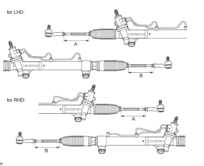
Standard Length Dimension Control range (for 4WD) Control range (for 2WD) for LHD A 153.7 to 155.7 mm (6.06 to 6.12 in.) 155.5 to 157.5 mm (6.13 to 6.20 in.) B for RHD A 153.7 to 155.7 mm (6.06 to 6.12 in.) 155.5 to 157.5 mm (6.13 to 6.20 in.) B Tech Tips
-
The values listed above are reference values.
-
The toe-in is adjusted in a step.
-
-
-
INSTALL POWER STEERING LINK ASSEMBLY
-
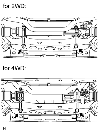
Install the steering link with the 2 bolts and 2 nuts.
- Torque:
- 95 N*m { 969 kgf*cm, 70 ft.*lbf }
Tech Tips
for 4WD:
If necessary, return the differential to its original position and install the differential mount.
-
-
INSTALL FRONT STABILIZER BAR
-
STABILIZE SUSPENSION
-
CONNECT STEERING GEAR OUTLET RETURN TUBE
-
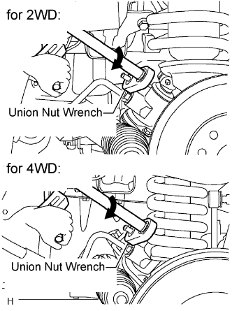
Using a union nut wrench, connect the outlet return tube.
- Torque:
- 44 N*m { 449 kgf*cm, 33 ft.*lbf }
Note
Use the formula to calculate special torque values for situations where a union nut wrench is combined with a torque wrench Click here.
-
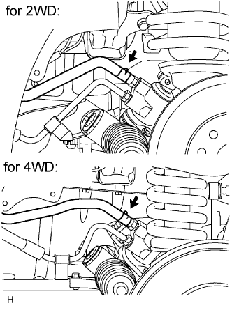
Install the hose with the clip.
-
-
CONNECT PRESSURE FEED TUBE ASSEMBLY
-
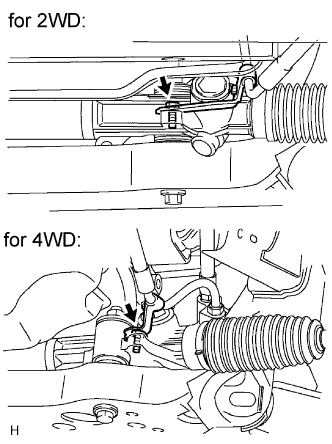
Install the pressure feed tube to the steering link with the bolt.
- Torque:
- 28 N*m { 286 kgf*cm, 21 ft.*lbf }
-
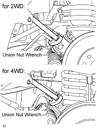
Using a union nut wrench, tighten the flare nut and connect the pressure feed tube.
- Torque:
- 44 N*m { 449 kgf*cm, 33 ft.*lbf }
Note
Use the formula to calculate special torque values for situations where a union nut wrench is combined with a torque wrench Click here.
-
-
CONNECT NO. 2 STEERING INTERMEDIATE SHAFT SUB-ASSEMBLY
-
Align the matchmarks on the steering intermediate shaft and steering link.
-
Install the bolt.
- Torque:
- 35 N*m { 357 kgf*cm, 26 ft.*lbf }
-
-
CONNECT STEERING SLIDING YOKE
-
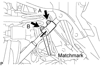
Align the matchmarks on the steering sliding yoke and steering intermediate shaft, and connect the steering sliding yoke to the steering intermediate shaft.
-
Install the bolt labeled B.
- Torque:
- 35 N*m { 357 kgf*cm, 26 ft.*lbf }
-
Tighten the bolt labeled A.
- Torque:
- 35 N*m { 357 kgf*cm, 26 ft.*lbf }
-
-
CONNECT TIE ROD END SUB-ASSEMBLY LH
-
Connect the tie rod end to the steering knuckle arm with the nut.
- Torque:
- 49 N*m { 500 kgf*cm, 36 ft.*lbf, for 2WD }
- 91 N*m { 928 kgf*cm, 67 ft.*lbf, for 4WD }
-
Install the cotter pin.
-
-
CONNECT TIE ROD END SUB-ASSEMBLY RH
Tech Tips
Use the same procedures described for the LH side.
-
INSTALL FRONT SIDE MEMBER TO FRONT SUSPENSION CROSSMEMBER BRACE
-
Install the crossmember brace with the 8 bolts.
- Torque:
- 50 N*m { 510 kgf*cm, 37 ft.*lbf }
-
-
INSTALL NO. 1 ENGINE UNDER COVER (for 4WD)
-
Install the under cover with the 4 bolts.
- Torque:
- 28 N*m { 286 kgf*cm, 21 ft.*lbf }
-
-
INSTALL NO. 2 ENGINE UNDER COVER (for 4WD)
-
Install the under cover with the 4 bolts.
- Torque:
- 28 N*m { 286 kgf*cm, 21 ft.*lbf }
-
-
INSTALL FRONT WHEEL
-
PLACE FRONT WHEELS FACING STRAIGHT AHEAD
-
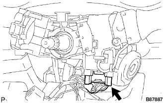
INSTALL WINDSHIELD WIPER SWITCH ASSEMBLY
-
Attach the claw to install the windshield washer switch.
Note
Do not push the claw with excessive force as damage may occur.
-
Connect the connectors.
-
-
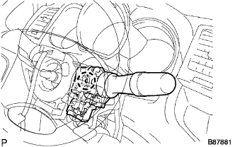
INSTALL HEADLIGHT DIMMER SWITCH ASSEMBLY
-
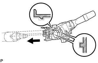
Install the headlight dimmer switch with the claw as shown in the illustration.
-
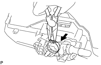
Install the headlight dimmer switch with the clamp.
-
Connect the connector.
-
-
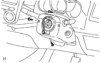
INSTALL SPIRAL CABLE SUB-ASSEMBLY
-
INSTALL STEERING COLUMN UPPER COVER
-
INSTALL STEERING COLUMN LOWER COVER
-
Install the cover lower with the 3 screws.
-
-
ADJUST SPIRAL CABLE
-
INSTALL STEERING WHEEL ASSEMBLY
-
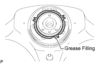
for 3 spoke:
Apply the silicon grease to the steering wheel.
-
Align the matchmarks on the steering wheel and main shaft.
-
Install the steering set nut.
- Torque:
- 50 N*m { 510 kgf*cm, 37 ft.*lbf }
-
-
INSPECT STEERING WHEEL CENTER POINT
-
INSTALL STEERING PAD ASSEMBLY
-
CONNECT CABLE TO NEGATIVE BATTERY TERMINAL
-
PERFORM INITIALIZATION
-
Perform initialization Click here.
Note
Certain systems need to be initialized after disconnecting and reconnecting the cable from the negative (-) battery terminal.
-
-
INSPECT SRS WARNING LIGHT
-
ADD POWER STEERING FLUID
-
BLEED AIR FROM POWER STEERING SYSTEM
-
CHECK FOR POWER STEERING FLUID LEAKAGE
-
INSPECT AND ADJUST FRONT WHEEL ALIGNMENT