OIL PUMP INSTALLATION

CAUTION / NOTICE / HINT
Note
This procedure includes the installation of small-head bolts. Refer to Small-Head Bolts of Basic Repair Hint to identify the small-head bolts.
PROCEDURE
-
INSTALL NO. 6 ENGINE COVER
-
INSTALL TIMING CHAIN COVER ASSEMBLY
-
INSTALL CRANKSHAFT TIMING GEAR OR SPROCKET
-
INSTALL NO. 2 CHAIN VIBRATION DAMPER
-
INSTALL NO. 1 CHAIN VIBRATION DAMPER
-
INSTALL IDLE SPROCKET ASSEMBLY
-
INSTALL NO. 1 CHAIN SUB-ASSEMBLY
-
INSTALL CHAIN TENSIONER SLIPPER
-
INSTALL NO. 1 CHAIN TENSIONER ASSEMBLY
-
INSPECT VALVE TIMING
-
INSTALL OIL PUMP DRIVE CHAIN SUB-ASSEMBLY
-
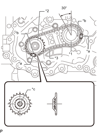
*1 Oil Pump Drive Sprocket *2 Oil Pump Drive Shaft Sprocket *3 Oil Pump Drive Chain Sub-assembly *a Mark Plate *b Timing Mark *c D Cut Plane Rotate the crankshaft timing gear key position 30° counterclockwise as shown in the illustration.
-
Set the D cut plane of the oil pump shaft at the position shown in the illustration.
-
Align the mark plates (yellow) on the oil pump drive sprocket, oil pump drive shaft sprocket and oil pump drive chain sub-assembly with the timing marks.
-
Install them to the oil pump shaft and crankshaft.
-
Temporarily install the oil pump drive shaft gear nut.
-
While pushing the chain damper spring, install the chain tensioner plate and chain damper spring.
-
Using the hexagonal portion of the camshaft, secure the camshaft.
-
Tighten the oil pump drive shaft gear nut.
- Torque:
- 36 N*m { 367 kgf*cm, 27 ft.*lbf }
-
-
INSTALL TIMING CHAIN OR BELT COVER SUB-ASSEMBLY
-
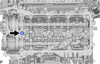
Remove any old packing remaining on the sealing surfaces before applying seal packing.
-
Clean the contact surfaces of the timing chain cover assembly, timing chain or belt cover sub-assembly and confirm that there is no oil, moisture or other foreign matter on the surfaces.
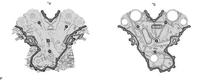
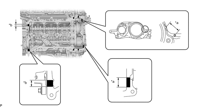
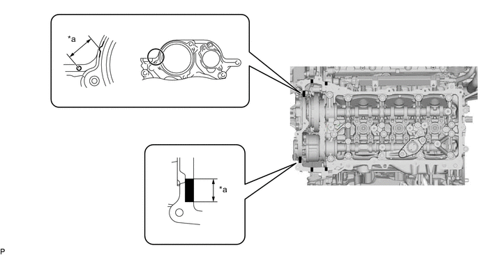
*a Timing Chain Cover Assembly Side *b Timing Chain or Belt Cover Sub-assembly Side 
Clean and Degrease - - Note
-
Be sure to clean and degrease the contact surfaces, especially the surfaces indicated in the illustration.
-
Check the bolts and bolt holes, and clean and degrease them.
-
-
Install 2 new water pump gaskets to the timing chain cover assembly.
-
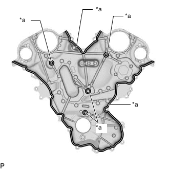
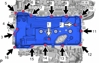
*a 3.0 to 4.0 mm (0.118 to 0.157 in.) 
Seal Packing Apply seal packing in a continuous line to the timing chain or belt cover sub-assembly as shown in the illustration.
Note
-
Using non-residue solvent, clean and remove any oil from the installation surface.
-
Check the bolts and bolt holes, and clean and degrease them.
-
Install the timing chain or belt cover sub-assembly within 3 minutes and tighten the bolts within 15 minutes of applying seal packing.
-
Do not add engine oil for at least 2 hours after installing the timing chain cover assembly.
-
Do not start the engine for at least 2 hours after installing the timing chain cover assembly.
-
-
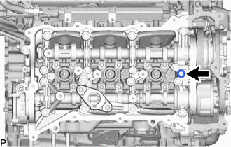
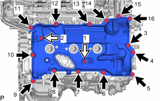
Temporarily install the timing chain or belt cover sub-assembly with the 27 bolts.
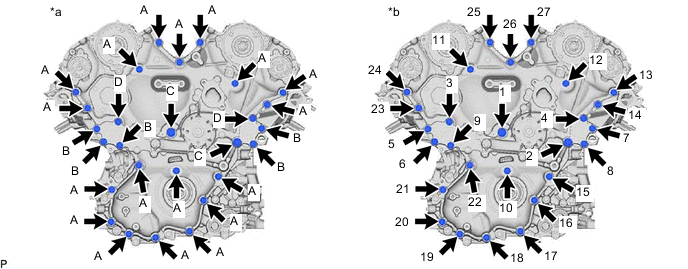
*a Type of bolt *b Tightening Order Bolt Length Item Length A 35 mm (1.38 in.) B 80 mm (3.15 in.) C 90 mm (3.54 in.) D 55 mm (2.17 in.) Note
Make sure that there is no oil on the bolt threads.
-
Tighten the 27 bolts in several steps, in the sequence shown in the illustration.
- Torque:
- Bolts A, B and D
- 21 N*m { 214 kgf*cm, 15 ft.*lbf }
- Bolt C
- 43 N*m { 438 kgf*cm, 32 ft.*lbf }
-
-
INSTALL TIMING CHAIN CASE OIL SEAL
-
INSTALL CRANKSHAFT PULLEY
-
INSTALL CRANKSHAFT DAMPER SUB-ASSEMBLY
-
INSTALL CRANKSHAFT PULLEY COVER
-
INSTALL CAM TIMING CONTROL MOTOR WITH EDU ASSEMBLY LH
-
INSTALL CAM TIMING CONTROL MOTOR WITH EDU ASSEMBLY RH
-
INSTALL CAM TIMING OIL CONTROL SOLENOID ASSEMBLY LH
-
INSTALL CAM TIMING OIL CONTROL SOLENOID ASSEMBLY RH
-
INSTALL SPARK PLUG TUBE GASKET
-
INSTALL CYLINDER HEAD COVER SUB-ASSEMBLY RH
-
Install a new No. 1 cylinder head cover gasket RH to the cylinder head cover sub-assembly RH.
-
Install 6 new No. 2 cylinder head cover gasket RH to the cylinder head cover sub-assembly RH.
-
Before applying seal packing black, cleanly remove any old sealant sticking to the part to be sealed.
-
Remove any remaining seal packing material and be careful not to drop any oil on the contact surfaces of the cylinder head sub-assembly, timing chain cover assembly and cylinder head cover sub-assembly.
-
Apply seal packing as shown in the illustration.
Seal packing Toyota Genuine Seal Packing Black, Three Bond 1207B or equivalent Standard seal diameter 3.0 to 6.0 mm (0.118 to 0.236 in.) Note
-
Remove any oil from the contact surface.
-
Install the cylinder head cover sub-assembly within 3 minutes and tighten the bolts within 15 minutes after applying seal packing.
*a Application Width 20 to 30 mm (0.787 to 1.181 in.) *b Application Range -
-
Install a new camshaft bearing cap oil hole gasket RH to the camshaft bearing cap.
-

Bolt A 
Bolt B Degrease the threads of the 14 cylinder head cover installation bolts (A).
-
Temporarily install the 2 VVT sensors with the 2 new bolts (B).
-
Temporarily install the cylinder head cover sub-assembly RH with the 14 bolts (A).
-
Temporarily install the cylinder head cover sub-assembly with the 16 bolts. Tighten the bolts uniformly in several steps.
- Torque:
- for bolt A
- 10 N*m { 102 kgf*cm, 7 ft.*lbf }
- for bolt B
- 7.5 N*m { 76 kgf*cm, 66 in.*lbf }
Bolt Length Item Length Bolt A 23.5 mm (0.925 in.) Bolt B 30 mm (1.18 in.) Note
Do not start the engine for at least 2 hours after installation.
-
Install the No. 1 intercooler air guide to the cylinder head cover sub-assembly RH.
- Torque:
- 10 N*m { 102 kgf*cm, 7 ft.*lbf }
-
-
INSTALL CYLINDER HEAD COVER SUB-ASSEMBLY LH
-
Install a new No. 1 cylinder head cover gasket LH to the cylinder head cover sub-assembly LH.
-
Install 6 new No. 2 cylinder head cover gasket LH to the cylinder head cover sub-assembly LH.
-
Before applying seal packing black, cleanly remove any old sealant sticking to the part to be sealed.
-
Remove any remaining seal packing material and be careful not to drop any oil on the contact surfaces of the cylinder head sub-assembly, timing chain cover assembly and cylinder head cover sub-assembly LH.
-
Apply seal packing as shown in the illustration.
Seal packing Toyota Genuine Seal Packing Black, Three Bond 1207B or equivalent Standard seal diameter 3.0 to 6.0 mm (0.118 to 0.236 in.) Note
-
Remove any oil from the contact surface.
-
Install the cylinder head cover sub-assembly LH within 3 minutes and tighten the bolts within 15 minutes after applying seal packing.
*a Application Width 20 to 30 mm (0.787 to 1.181 in.) - - -
-
Install a new camshaft bearing cap oil hole gasket LH to the camshaft bearing cap.
-
Bolt A Bolt B Degrease the threads of the 14 cylinder head cover installation bolts (A).
-
Temporarily install the 2 VVT sensors with the 2 new bolts (B).
-
Temporarily install the cylinder head cover sub-assembly RH with the 14 bolts (A).
-
Temporarily install the cylinder head cover sub-assembly LH with the 16 bolts. Tighten the bolts uniformly in several steps.
- Torque:
- for bolt A
- 10 N*m { 102 kgf*cm, 7 ft.*lbf }
- for bolt B
- 7.5 N*m { 76 kgf*cm, 66 in.*lbf }
Bolt Length Item Length Bolt A 23.5 mm (0.925 in.) Bolt B 30 mm (1.18 in.) Note
Do not start the engine for at least 2 hours after installation.
-
Install the No. 1 intercooler air guide to the cylinder head cover sub-assembly LH.
- Torque:
- 10 N*m { 102 kgf*cm, 7 ft.*lbf }
-
-
INSTALL NO. 2 ENGINE COVER RH
-
INSTALL NO. 2 ENGINE COVER LH
-
INSTALL SPARK PLUG
-
INSTALL OIL FILTER BRACKET SUB-ASSEMBLY
-
Install 2 new gaskets to the timing chain cover assembly.
-
Install the oil filter bracket sub-assembly with the 3 bolts.
- Torque:
- 21 N*m { 214 kgf*cm, 15 ft.*lbf }
-
-
INSTALL IGNITION COIL ASSEMBLY
-
INSTALL GENERATOR BRACKET SUB-ASSEMBLY
-
INSTALL WATER INLET ASSEMBLY
-
INSTALL V-RIBBED BELT TENSIONER ASSEMBLY
-
INSTALL IDLER PULLEY SUB-ASSEMBLY
-
INSTALL WATER PUMP PULLEY
-
CONNECT NO. 4 RADIATOR HOSE
-
INSTALL WATER OUTLET PIPE WATER BY-PASS JOINT
-
INSTALL NO. 2 WATER OUTLET PIPE
-
INSTALL NO. 1 WATER OUTLET PIPE
-
INSTALL NO. 11 ENGINE WIRE
-
INSTALL NO. 2 WATER BY-PASS PIPE SUB-ASSEMBLY
-
INSTALL WATER CONTROL VALVE
-
INSTALL INTAKE PIPE STAY
-
INSTALL NO. 1 TURBO PRESSURE SENSOR
-
CONNECT NO. 1 WATER BY-PASS PIPE
-
Connect the No. 1 water by-pass pipe with the 3 bolts.
- Torque:
- 21 N*m { 214 kgf*cm, 15 ft.*lbf }
-
-
CONNECT WATER HOSE
-
CONNECT NO. 1 TURBO WATER PIPE SUB-ASSEMBLY
-
Connect the No. 1 turbo water pipe sub-assembly to the cylinder head cover sub-assembly RH with the bolt.
- Torque:
- 10 N*m { 102 kgf*cm, 7 ft.*lbf }
-
-
INSTALL TURBO WATER PIPE STAY
-
Install the turbo water pipe stay with the 2 bolts.
- Torque:
- 10 N*m { 102 kgf*cm, 7 ft.*lbf }
-
-
INSTALL NO. 2 AIR INLET DUCT
-
Connect the No. 2 air inlet duct to the compressor inlet elbow.
-
Tighten the hose clamp.
- Torque:
- 4.0 N*m { 41 kgf*cm, 35 in.*lbf }
-
Install the bolt.
- Torque:
- 10 N*m { 102 kgf*cm, 7 ft.*lbf }
-
Attach the 2 clamps and connect the vacuum hose.
-
-
CONNECT NO. 2 PCV TUBE
-
INSTALL NO. 1 AIR HOSE
-
Install the No. 1 air hose to the No. 1 compressor outlet elbow.
-
Tighten the hose clamp.
- Torque:
- 6.3 N*m { 64 kgf*cm, 56 in.*lbf }
-
-
INSTALL NO. 1 AIR INLET DUCT
-
Connect the No. 1 air inlet duct to the compressor inlet elbow.
-
Tighten the hose clamp.
- Torque:
- 4.0 N*m { 41 kgf*cm, 35 in.*lbf }
-
Install the bolt.
- Torque:
- 10 N*m { 102 kgf*cm, 7 ft.*lbf }
-
Attach the 2 clamps and connect the vacuum hose.
-
-
CONNECT NO. 1 PCV TUBE
-
INSTALL ENGINE OIL LEVEL DIPSTICK GUIDE
-
INSTALL FUEL PUMP ASSEMBLY (for Bank 2)
-
INSTALL FUEL PUMP ASSEMBLY (for Bank 1)
-
INSTALL GENERATOR ASSEMBLY
-
INSTALL COMPRESSOR ASSEMBLY WITH PULLEY
-
for 2WD:
-
for AWD:
-