DYNAMIC TORQUE CONTROL AWD SYSTEM, Diagnostic DTC:C1337/91

| DTC Code | DTC Name |
|---|---|
| C1337/91 | Diameter of the Tire is not Uniform |
DESCRIPTION
The 4WD ECU assembly stores this DTC if a difference in tire size is detected.
| DTC No. | Detection Item | DTC Detection Condition | Trouble Area |
|---|---|---|---|
| C1337/91 | Diameter of the Tire is not Uniform | When the following continues for 36 seconds or more: At a vehicle speed of 30 km/h (18.6 mph) or more, the average speed difference between the front wheel and rear wheel is 4% or more. |
|
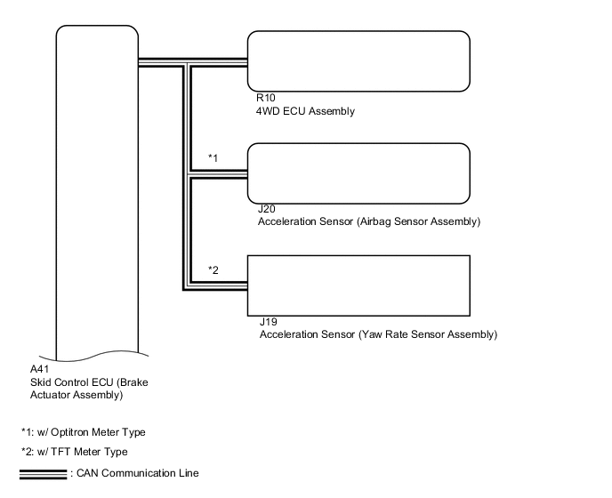
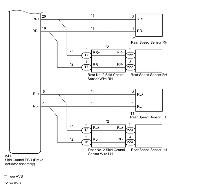
WIRING DIAGRAM

CAUTION / NOTICE / HINT
Note
When the 4WD ECU assembly is replaced with a known good one from another vehicle, it is necessary to perform calibration.
PROCEDURE
-
CHECK TIRE CONDITION
-
Check the size and condition of all 4 tires.
Tech Tips
This DTC is output when tire deformation or a difference in tire size is detected.
OK The diameter and air pressure of all 4 tires are the same. Result Proceed to OK NG
NG 
PERFORM AIR PRESSURE ADJUSTMENT OR REPLACE TIRES SO THAT ALL 4 TIRES ARE SAME IN SIZE Click here
OK 
-
-
CHECK FOR DTC
-
Clear the DTCs.
Chassis > Four Wheel Drive > Clear DTCs -
Start the engine.
-
Drive the vehicle at a speed of 30 km/h (19 mph) or more so that the same DTC is output.
Chassis > Four Wheel Drive > Trouble Codes -
Check if the speed sensor DTC (vehicle stability control system DTC) is output.
Chassis > ABS/VSC/TRC/EPB > Trouble Codes -
Read the DTCs using the GTS.
Result Result Proceed to Only DTC C1377/91 is output (w/o AVS) A Only DTC C1377/91 is output (w/ AVS) B DTCs are not output C Speed sensor DTCs (vehicle stability control system DTC) are output D
B 
CHECK HARNESS AND CONNECTOR (SKID CONTROL SENSOR WIRE - BRAKE ACTUATOR ASSEMBLY) Click here
C
CHECK FOR INTERMITTENT PROBLEMS Click here
D
REPAIR CIRCUIT INDICATED BY OUTPUT CODE (VEHICLE STABILITY CONTROL SYSTEM) Click here
A
-
-
CHECK HARNESS AND CONNECTOR (SPEED SENSOR - BRAKE ACTUATOR ASSEMBLY)
-
Make sure that there is no looseness at the locking part and the connecting part of the connectors.
-
Turn the engine switch off.
-
Disconnect the A41 skid control ECU (brake actuator assembly) connector.
-
Disconnect the A92, A93, T1 and/or T2 speed sensor connector(s).
-
Measure the resistance according to the value(s) in the table below.
Standard Resistance for Front RH: Tester Connection Condition Specified Condition A41-7 (FR+) - A93-3 (FR+) Always Below 1 Ω A41-6 (FR-) - A93-4 (FR-) Always A41-7 (FR+) or A93-3 (FR+) - Body ground and other terminals Always 10 kΩ or higher A41-6 (FR-) or A93-4 (FR-) - Body ground and other terminals Always for Front LH: Tester Connection Condition Specified Condition A41-22 (FL+) - A92-3 (FL+) Always Below 1 Ω A41-21 (FL-) - A92-4 (FL-) Always A41-22 (FL+) or A92-3 (FL+) - Body ground and other terminals Always 10 kΩ or higher A41-21 (FL-) or A92-4 (FL-) - Body ground and other terminals Always for Rear RH: Tester Connection Condition Specified Condition A41-20 (RR+) - T2-2 (RR+) Always Below 1 Ω A41-19 (RR-) - T2-1 (RR-) Always A41-20 (RR+) or T2-2 (RR+) - Body ground and other terminals Always 10 kΩ or higher A41-19 (RR-) or T2-1 (RR-) - Body ground and other terminals Always for Rear LH: Tester Connection Condition Specified Condition A41-5 (RL+) - T1-3 (RL+) Always Below 1 Ω A41-4 (RL-) - T1-1 (RL-) Always A41-5 (RL+) or T1-3 (RL+) - Body ground and other terminals Always 10 kΩ or higher A41-4 (RL-) or T1-1 (RL-) - Body ground and other terminals Always Result Proceed to OK NG -
Connect the A92, A93, T1 and/or T2 speed sensor connector(s).
-
Connect the A41 skid control ECU (brake actuator assembly) connector.
OK
GO TO STEP 6 Click here
NG
REPAIR OR REPLACE HARNESS OR CONNECTOR
-
-
CHECK HARNESS AND CONNECTOR (SKID CONTROL SENSOR WIRE - BRAKE ACTUATOR ASSEMBLY)
-
Make sure that there is no looseness at the locking part and the connecting part of the connectors.
-
Disconnect the A41 skid control ECU (brake actuator assembly) connector.
-
Disconnect the A90, A91, T7 and/or T8 skid control sensor wire connector(s).
-
Measure the resistance according to the value(s) in the table below.
Standard Resistance for Front RH: Tester Connection Condition Specified Condition A41-7 (FR+) - A91-3 (FR+) Always Below 1 Ω A41-6 (FR-) - A91-4 (FR-) Always A41-7 (FR+) or A91-3 (FR+) - Body ground and other terminals Always 10 kΩ or higher A41-6 (FR-) or A91-4 (FR-) - Body ground and other terminals Always for Front LH: Tester Connection Condition Specified Condition A41-22 (FL+) - A90-3 (FL+) Always Below 1 Ω A41-21 (FL-) - A90-4 (FL-) Always A41-22 (FL+) or A90-3 (FL+) - Body ground and other terminals Always 10 kΩ or higher A41-21 (FL-) or A90-4 (FL-) - Body ground and other terminals Always for Rear RH: Tester Connection Condition Specified Condition A41-20 (RR+) - T7-2 (RR+) Always Below 1 Ω A41-19 (RR-) - T7-1 (RR-) Always A41-20 (RR+) or T7-2 (RR+) - Body ground and other terminals Always 10 kΩ or higher A41-19 (RR-) or T7-1 (RR-) - Body ground and other terminals Always for Rear LH: Tester Connection Condition Specified Condition A41-5 (RL+) - T8-3 (RL+) Always Below 1 Ω A41-4 (RL-) - T8-1 (RL-) Always A41-5 (RL+) or T8-3 (RL+) - Body ground and other terminals Always 10 kΩ or higher A41-4 (RL-) or T8-1 (RL-) - Body ground and other terminals Always Result Proceed to OK NG -
Connect the A90, A91, T7 and/or T8 skid control sensor wire connector(s).
-
Connect the A41 skid control ECU (brake actuator assembly) connector.
NG
REPAIR OR REPLACE HARNESS OR CONNECTOR
OK
-
-
INSPECT SKID CONTROL SENSOR WIRE
-
Make sure that there is no looseness at the locking part and the connecting part of the connectors.
-
Turn the engine switch off.
-
Disconnect the A90, A91, z20 and/or z21 front skid control sensor wire connector(s).
-
Measure the resistance according to the value(s) in the table below.
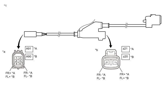
*A for RH *B for LH *1 Front Skid Control Sensor Wire - - *a Front view of wire harness connector
(to Vehicle Side Connector)
*b Front view of wire harness connector
(to Front Speed Sensor Side Connector)
Standard Resistance for Front Skid Control Sensor Wire RH: Tester Connection Condition Specified Condition z21-1 (FR+) - A91-3 (FR+) Always Below 1 Ω z21-2 (FR-) - A91-4 (FR-) Always z21-1 (FR+) or A91-3 (FR+) - Body ground and other terminals Always 10 kΩ or higher z21-2 (FR-) or A91-4 (FR-) - Body ground and other terminals Always for Front Skid Control Sensor Wire LH: Tester Connection Condition Specified Condition z20-1 (FL+) - A90-3 (FL+) Always Below 1 Ω z20-2 (FL-) - A90-4 (FL-) Always z20-1 (FL+) or A90-3 (FL+) - Body ground and other terminals Always 10 kΩ or higher z20-2 (FL-) or A90-4 (FL-) - Body ground and other terminals Always -
Connect the A90, A91, z20 and/or z21 front skid control sensor wire connector(s).
-
Disconnect the T7, T8, z22 and/or z23 rear No. 2 skid control sensor wire connector(s).
-
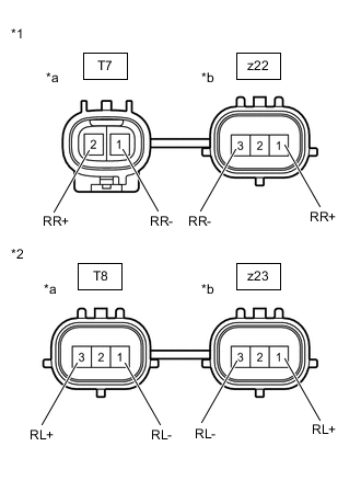
*1 Rear No. 2 Skid Control Sensor Wire RH *2 Rear No. 2 Skid Control Sensor Wire LH *a Front view of wire harness connector
(to Vehicle Side Connector)
*b Front view of wire harness connector
(to Rear Speed Sensor Side Connector)
Measure the resistance according to the value(s) in the table below.
Standard Resistance for Rear No. 2 Skid Control Sensor Wire RH: Tester Connection Condition Specified Condition z22-1 (RR+) - T7-2 (RR+) Always Below 1 Ω z22-3 (RR-) - T7-1 (RR-) Always z22-1 (RR+) or T7-2 (RR+) - Body ground and other terminals Always 10 kΩ or higher z22-3 (RR-) or T7-1 (RR-) - Body ground and other terminals Always for Rear No. 2 Skid Control Sensor Wire LH: Tester Connection Condition Specified Condition z23-1 (RL+) - T8-3 (RL+) Always Below 1 Ω z23-3 (RL-) - T8-1 (RL-) Always z23-1 (RL+) or T8-3 (RL+) - Body ground and other terminals Always 10 kΩ or higher z23-3 (RL-) or T8-1 (RL-) - Body ground and other terminals Always -
Connect the T7, T8, z22 and/or z23 rear No. 2 skid control sensor wire connector(s).
Result Proceed to OK NG
NG
REPAIR OR REPLACE SKID CONTROL SENSOR WIRE
OK
-
-
PERFORM TEST MODE (SIGNAL CHECK)
-
Turn the engine switch off.
-
Perform the sensor check in the Test Mode procedure.
Chassis > ABS/VSC/TRC/EPB > UtilityTester Display Signal Check OK All Test Mode (signal check) inspection items are normal. Result Proceed to OK NG
NG
CHECK SPEED SENSOR ROTOR Click here
OK
-
-
RECONFIRM DTC
-
Clear the DTCs.
Chassis > Four Wheel Drive > Clear DTCs -
Start the engine.
-
Drive the vehicle at a speed of 30 km/h (19 mph) or more and check that the same DTC is output.
Chassis > Four Wheel Drive > Trouble CodesResult Result Proceed to DTC is not output A DTC is output B
A
CHECK FOR INTERMITTENT PROBLEMS Click here
B
REPLACE BRAKE ACTUATOR ASSEMBLY Click here
-
-
CHECK SPEED SENSOR ROTOR
-
Turn the engine switch off.
-
Remove the front speed sensor rotor (front axle hub sub-assembly) or rear speed sensor rotor (rear axle hub and bearing assembly).
for Front: Click here
for Rear: Click here
-
Check the speed sensor rotor.
OK There is no foreign matter, scratches or oil on the rotors. Tech Tips
-
If the front speed sensor rotor needs to be replaced, replace the front axle hub bearing assembly.
-
If the rear speed sensor rotor needs to be replaced, replace the rear axle hub and bearing assembly.
Result Proceed to OK NG -
NG
CLEAN OR REPLACE SPEED SENSOR ROTOR
OK
-
-
REPLACE SPEED SENSOR
-
Turn the engine switch off.
-
Replace the front speed sensor or the rear speed sensor.
for Front: Click here
for Rear: Click here
Result Proceed to NEXT
NEXT
-
-
RECONFIRM DTC
-
Clear the DTCs.
Chassis > Four Wheel Drive > Clear DTCs -
Start the engine.
-
Drive the vehicle at a speed of 30 km/h (19 mph) or more and check that the same DTC is output.
Chassis > Four Wheel Drive > Trouble CodesResult Result Proceed to DTC is output A DTC is not output B Tech Tips
Reinstall the sensor, connectors, etc. and restore the vehicle to its prior condition before rechecking DTCs.
B
END
A
-
-
REPLACE BRAKE ACTUATOR ASSEMBLY
-
Replace the skid control ECU (brake actuator assembly).
Result Proceed to NEXT
NEXT
-
-
RECONFIRM DTC
-
Clear the DTCs.
Chassis > Four Wheel Drive > Clear DTCs -
Start the engine.
-
Drive the vehicle at a speed of 30 km/h (19 mph) or more and check that the same DTC is output.
Chassis > Four Wheel Drive > Trouble CodesResult Result Proceed to DTC is not output A DTC is output B
A
END
B
REPLACE 4WD ECU ASSEMBLY Click here
-