REAR AXLE CARRIER(for 2WD) REMOVAL
CAUTION / NOTICE / HINT
The necessary procedures (adjustment, calibration, initialization, or registration) that must be performed after parts are removed and installed, or replaced during rear axle carrier sub-assembly removal/installation are shown below.
| Replaced Part or Performed Procedure | Necessary Procedure | Effect/Inoperative Function when Necessary Procedure not Performed | Link |
|---|---|---|---|
| Rear wheel alignment adjustment |
|
|
|
| Removal/installation of rear height control sensor sub-assembly LH*1 | Initialize headlight ECU sub-assembly LH | Automatic headlight beam level control system | |
| Suspension, tires, etc. (The vehicle height changes because of suspension or tire replacement)*1 |
-
*1: w/ Height Control Sensor
Tech Tips
-
Use the same procedure for the RH side and LH side.
-
The following procedure is for the LH side.
PROCEDURE
-
REMOVE REAR WHEEL
-
SEPARATE REAR DISC BRAKE CALIPER ASSEMBLY
-
REMOVE REAR DISC
-
DISCONNECT SKID CONTROL SENSOR WIRE
-
REMOVE REAR AXLE HUB AND BEARING ASSEMBLY
-
REMOVE FLEXIBLE HOSE BRACKET
-
Remove the bolt and flexible hose bracket from the rear axle carrier sub-assembly.
-
-
REMOVE REAR HEIGHT CONTROL SENSOR SUB-ASSEMBLY LH (w/ Height Control Sensor)
-
REMOVE REAR STABILIZER LINK ASSEMBLY
-
REMOVE REAR COIL SPRING
-
REMOVE REAR LOWER COIL SPRING INSULATOR
-
REMOVE REAR NO. 1 SUSPENSION ARM ASSEMBLY
-
REMOVE REAR AXLE CARRIER SUB-ASSEMBLY
-
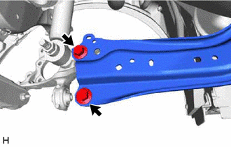
Loosen the 2 bolts of the rear trailing arm assembly.
-
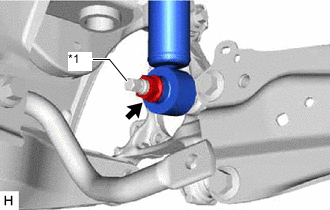
*1 Rear Axle Carrier Pin Loosen the nut of the rear shock absorber assembly.
Note
Hold the rear axle carrier pin while rotating the nut.
-
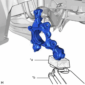
*a Wooden Block *b Jack Using a jack and a wooden block, support the rear axle carrier sub-assembly.
Note
-
When jacking up the rear axle carrier sub-assembly, be sure to jack it up slowly.
-
Make sure to perform this operation with the vehicle kept as low as possible.
-
-
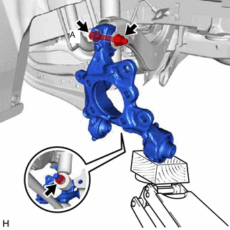
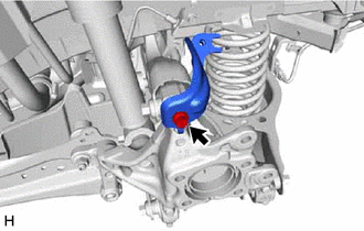
Loosen the bolt (A).
Note
Because the nut has its own stopper, do not turn the nut. Loosen the bolt with the nut secured.
-
Remove the 2 bolts and separate the rear trailing arm assembly from the rear axle carrier sub-assembly.
-
Remove the nut and separate the rear shock absorber assembly from the rear axle carrier sub-assembly.
Note
Hold the rear axle carrier pin while rotating the nut.
-
Remove the bolt (A), nut and rear axle carrier sub-assembly from the rear upper control arm assembly.
Note
Because the nut has its own stopper, do not turn the nut. Loosen the bolt with the nut secured.
-