CYLINDER BLOCK REASSEMBLY
CAUTION / NOTICE / HINT
Note
This procedure includes the installation of small-head bolts. Refer to Small-Head Bolts of Basic Repair Hint to identify the small-head bolts.
Tech Tips
Perform "Inspection After Repairs" after replacing the piston or piston ring.
-
w/ Canister Pump Module:
-
w/o Canister Pump Module:
PROCEDURE
-
INSTALL OIL PRESSURE SENDER GAUGE ASSEMBLY (w/ GPF)
-
Remove any oil from the threads of the oil pressure sender gauge assembly.
-
Apply adhesive to 2 or 3 threads of the oil pressure sender gauge assembly.
Adhesive TOYOTA Genuine Adhesive 1344, Three Bond 1344 or equivalent. Note
Do not let adhesive adhere to the oil hole.
-
Using a 27 mm deep socket wrench, install the oil pressure sender gauge assembly.
- Torque:
- 15 N*m { 153 kgf*cm, 11 ft.*lbf }
Note
Do not start the engine within 1 hour of installation.
-
-
INSTALL NO. 1 PLUG WITH HEAD TAPER SCREW
-
Apply adhesive to 2 or 3 threads of the No. 1 plug with head taper screw.
Adhesive Toyota Genuine Adhesive 1344, Three Bond 1344 or equivalent Note
-
After applying adhesive 1344, install the No. 1 plug with head taper screw within 3 minutes.
-
Do not pour in engine oil within 1.0 hours of installing the No. 1 plug with head taper screw and leave the sub-assembly as it is.
-
-
Install the No. 1 plug with head taper screw to the cylinder block sub-assembly.
- Torque:
- 15 N*m { 153 kgf*cm, 11 ft.*lbf }
-
-
INSTALL CYLINDER BLOCK PLUG WITH HEAD STRAIGHT SCREW
-
Temporarily install a new gasket and cylinder block plug with head straight screw to the cylinder block sub-assembly.
-
Using a 10 mm hexagon socket, tighten the cylinder block plug with head straight screw.
- Torque:
- 60 N*m { 612 kgf*cm, 44 ft.*lbf }
-
-
INSTALL CYLINDER BLOCK INSERT SPACER
-
Install a new gasket and cylinder block insert spacer to the cylinder block sub-assembly.
- Torque:
- 66 N*m { 673 kgf*cm, 49 ft.*lbf }
-
-
INSTALL OIL PRESSURE SWITCHING VALVE ASSEMBLY (w/ GPF)
-
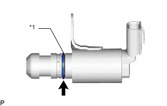
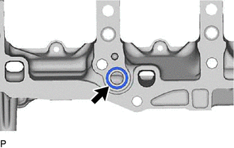
*1 O-Ring Apply a light coat of engine oil to the O-ring of the oil pressure switching valve assembly.
-
Install the oil pressure switching valve assembly to the cylinder block insert spacer with the bolt.
- Torque:
- 10 N*m { 102 kgf*cm, 7 ft.*lbf }
Note
-
When reusing the oil pressure switching valve assembly, inspect the O-ring.
-
Make sure that the O-ring is not cracked or jammed when installing the oil pressure switching valve assembly.
-
-
INSTALL NO. 1 OIL NOZZLE SUB-ASSEMBLY
-
Using a 5 mm hexagon wrench, install the No. 1 oil nozzle sub-assemblies with the 6 bolt
- Torque:
- 10 N*m { 102 kgf*cm, 7 ft.*lbf }
-
-
INSTALL PISTON SUB-ASSEMBLY WITH PIN
Tech Tips
Perform "Inspection After Repairs" after replacing the piston.
-
w/ Canister Pump Module:
-
w/o Canister Pump Module:
-
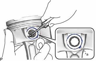
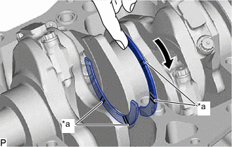
*a Cutout Portion Using a screwdriver, install a new piston pin hole snap ring at one end of the piston pin hole.
Tech Tips
Confirm that the end gap of the snap ring is not aligned with the pin hole cutout portion of the piston.
-
Gradually heat the piston to approximately 80°C (176°F).
-
Coat the piston pin with engine oil.
-
for Bank 1:
-
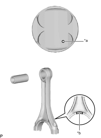
*a Piston RH *b Piston Matchmark (Protrusion) Align the piston matchmark (protrusion) of the piston and connecting rod, and push in the piston pin with your thumb.
Tech Tips
-
The piston and pin are a matched set.
-
Take care as the piston matchmark (protrusion) on the piston RH connecting rod is reversed for the piston LH.
-
-
Check the fitting condition between the piston and piston pin by trying to move the piston back and forth on the piston pin.
-
-
for Bank 2:
-
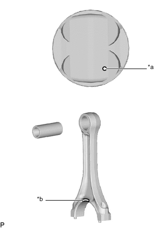
*a Piston LH *b Piston Matchmark (Protrusion) Align the piston matchmark (protrusion) of the piston and connecting rod, and push in the piston pin with your thumb.
Tech Tips
-
The piston and pin are a matched set.
-
Take care as the piston matchmark (protrusion) on the piston RH connecting rod is reversed for the piston LH.
-
-
Check the fitting condition between the piston and piston pin by trying to move the piston back and forth on the piston pin.
-
-
*a Cutout Portion Using a screwdriver, install a new piston pin hole snap ring at the other end of the piston pin hole.
Tech Tips
Confirm that the end gap of the snap ring is not aligned with the pin hole cutout portion of the piston.
-
-
INSTALL PISTON RING SET
Tech Tips
Perform "Inspection After Repairs" after replacing the piston ring.
-
w/ Canister Pump Module:
-
w/o Canister Pump Module:
-
Install the oil ring expander and 2 side rails by hand.
-
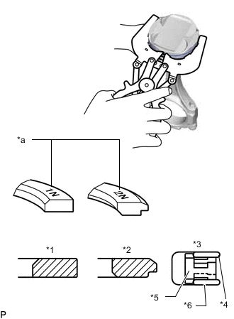
*1 No. 1 Compression Ring *2 No. 2 Compression Ring *3 Oil Ring *4 Upper Side Rail *5 Oil Ring Expander *6 Lower Side Rail *a Code Mark Using a piston ring expander, install the 2 compression rings so that the painted marks are positioned as shown in the illustration.
Tech Tips
-
Install the No. 1 compression ring with the code mark (1N) facing upward.
-
Install the No. 2 compression ring with the code mark (2N) facing upward.
-
-
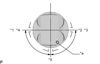
*1 No. 1 Compression Ring *2 No. 2 Compression Ring *3 Lower Side Rail *4 Upper Side Rail *5 Expander *a Piston Matchmark (Arrow) Position the piston rings so that the ring ends are as shown in the illustration.
Note
Do not align the ring ends.
-
-
INSTALL CRANKSHAFT BEARING
-
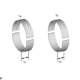
*a No. 1 and No. 4 Journal Bearing *b No. 2 and No. 3 Journal Bearing *c 21.0 mm (0.827 in.) *d 19.0 mm (0.748 in.) Clean the main journal and both surfaces of the bearings.
Note
Main bearings come in widths between 19.0 mm (0.748 in.) and 21.0 mm (0.827 in.). Install the 21.0 mm (0.827 in.) bearings in the No. 1 and No. 4 cylinder block journal positions with the main bearing cap. Install the 19.0 mm (0.748 in.) bearings in the No. 2 and No. 3 positions.
-
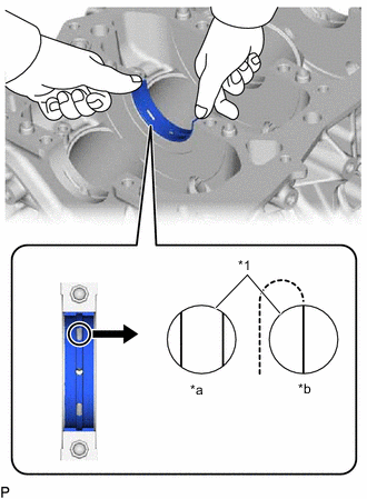
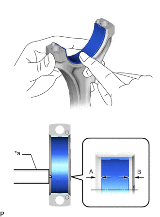
*1 Upper Crankshaft Bearing *a Correct *b Incorrect Install the upper crankshaft bearing.
-
Install the upper crankshaft bearings to the cylinder block sub-assembly as shown in the illustration.
Note
-
Do not apply engine oil to the bearings and the contact surfaces.
-
Both sides of the oil groove in the cylinder block sub-assembly should be visible through the oil feed holes in the bearing. The amount visible on each side of the holes should be equal.
-
Do not allow coolant to come into contact with the bearing inner surface.
-
If any coolant comes into contact with the bearing inner surface, replace the bearing with a new one.
-
-
-
*a Vernier Caliper Install the lower crankshaft bearing.
-
Install the lower crankshaft bearings to the crankshaft bearing caps.
-
Using a vernier caliper, measure the distance between the crankshaft bearing cap edge and the lower crankshaft bearing edge.
Standard dimension (A - B or B - A) 0.7 mm (0.0276 in.) or less Note
-
Do not apply engine oil to the crankshaft bearings and the contact surfaces.
-
Do not allow coolant to come into contact with the bearing inner surface.
-
If any coolant comes into contact with the bearing inner surface, replace the bearing with a new one.
-
-
-
-
INSTALL CRANKSHAFT THRUST WASHER SET
-
Apply engine oil to the crankshaft thrust washer.
-
*a Oil Grooves Install the 2 upper crankshaft thrust washers under the No. 2 journal position of the cylinder block sub-assembly with the oil grooves facing outward.
Note
Make sure to correctly install the crankshaft thrust washer set.
-
-
INSTALL CRANKSHAFT
-
Apply engine oil to the crankshaft bearing (upper), and then place the crankshaft on the cylinder block sub-assembly.
-
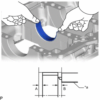
Install a new gasket to the crankshaft bearing cap sub-assembly.
-
Apply engine oil to the crankshaft bearing (lower).
-
*a 4.5 to 5.5 mm (0.177 to 0.216 in.) *b 2.5 to 6.5 mm (0.098 to 0.255 in.) *c 2.5 to 3.5 mm (0.098 to 0.137 in.) 
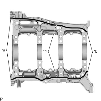
Seal Packing Apply seal packing black to the crankshaft bearing cap sub-assembly at the points shown in the illustration.
Note
-
Clean and degrease the installation surface using non-residue solvent and brake cleaner.
-
Check, clean and degrease the bolt and bolt hole.
-
Install the part within 3 minutes and tighten the bolts within 15 minutes after applying seal packing.
-
Do not pour engine oil within 2 hours of the installation.
-
Do not start the engine within 2 hours of the installation.
-
-
Check the protrusion of the crankshaft bearing cap sub-assembly and journal number, and then temporarily place the crankshaft bearing cap sub-assembly on the cylinder block sub-assembly.
Note
-
Check the protrusion of the crankshaft bearing cap and journal number.
-
Install the crankshaft bearing cap sub-assembly as shown in the illustration.
-
-
Using a plastic-faced hammer, lightly tap the crankshaft bearing cap sub-assembly to securely insert it.
-
Apply engine oil to the threads and beneath the head of the crankshaft bearing cap set bolt.
Note
Tighten the crankshaft bearing cap set bolts by the plastic region tightening method.
-
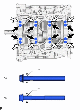
*a Bolt A (Bolt Diameter 12 mm (0.472 in.)) *b Bolt B (Bolt Diameter 11 mm (0.433 in.)) *c Measurement Area 
Bolt A 
Bolt B Apply engine oil to the threads and beneath the head of the crankshaft bearing cap set bolts, and install the 16 crankshaft bearing cap set bolts at the positions shown in the illustration.
Note
The thickness of the crankshaft bearing cap set bolt differs. Therefore, check this at installation.
-
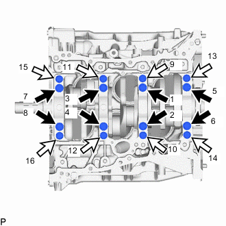
Bolt A Bolt B Temporarily install in 2 or 3 steps in the order shown in the illustration and tighten to the specified torque (1st Time).
- Torque:
- 30 N*m { 306 kgf*cm, 22 ft.*lbf }
Note
-
The tightening procedure is different for bolt A and bolt B.
-
Tighten the bolts while checking that the crankshaft rotates smoothly.
-
Tighten to the specified torque in the order shown in the illustration (2nd Time).
- Torque:
- for bolt A
- 61 N*m { 622 kgf*cm, 45 ft.*lbf }
- for bolt B.
- 90 N*m { 918 kgf*cm, 66 ft.*lbf }
Note
Tighten the bolts while checking that the crankshaft rotates smoothly.
-
Place paint marks on the front side of the crankshaft bearing cap set bolt heads.
-
Retighten the crankshaft bearing cap set bolts 90° in the tightening order, using the paint marks on bolt A as the indicator.
Note
Tighten the bolts while checking that the crankshaft rotates smoothly.
-
Retighten the crankshaft bearing cap set bolts 45° in the tightening order, using the paint marks on bolt A as the indicator.
Note
Tighten the bolts while checking that the crankshaft rotates smoothly.
-
Retighten the crankshaft bearing cap set bolts 90° in the tightening order, using the paint marks on bolt B as the indicator.
Note
Tighten the bolts while checking that the crankshaft rotates smoothly.
-
Check that the paint marks on bolt B are now at a 90° angle from their original position.
-
Check that the paint marks on bolt A are now at a 135° angle from their original position.
-
Install the 9 crankshaft bearing cap bolts.
-
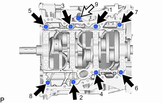
Bolt A (Length Beneath Head 80 mm (3.149 in.)) Bolt B (Length Beneath Head 35 mm (1.377 in.)) Tighten to the specified torque in the order shown in the illustration.
- Torque:
- 46 N*m { 469 kgf*cm, 34 ft.*lbf }
-
-
INSTALL CONNECTING ROD BEARING
-
Install the connecting rod bearings to the connecting rod and connecting rod cap.
-
*a Vernier Caliper Using a vernier caliper, measure the distance between each connecting rod bearing edge and the connecting rod edges, and the connecting rod cap edges respectively.
Standard dimension (A - B or B - A) 0.7 mm (0.0276 in.) or less Note
Do not apply engine oil to the bearings and the contact surfaces.
-
-
INSTALL PISTON SUB-ASSEMBLY WITH CONNECTING ROD
-
Apply engine oil to the cylinder walls, the pistons, and the surfaces of the connecting rod bearings.
-
*1 No. 1 Compression Ring *2 No. 2 Compression Ring *3 Lower Side Rail *4 Upper Side Rail *5 Oil Ring Expander *a Piston Matchmark (Arrow) Position the piston rings so that the ring ends are as shown in the illustration.
Note
Do not align the ring ends.
-
Using a piston ring compressor, push the correctly numbered piston and connecting rod assembly into the cylinder with the piston matchmark of the piston facing forward.
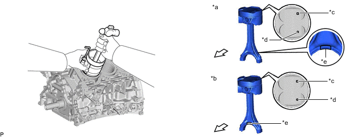
*a Piston RH *b Piston LH *c Piston Pin Size Identification Mark *d Piston Matchmark (Arrow) *e Piston Matchmark (Protrusion) - - Engine Front - - Note
-
Take care as the piston matchmark (protrusion) on the piston RH connecting rod is reversed for the piston LH.
-
When inserting the piston with connecting rod, install it so that the connecting rod does not damage the wall of the cylinder and crank pin.
-
Do not change piston and piston pin combinations.
-
-
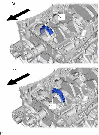
*a for Bank 1 (Piston RH) *b for Bank 2 (Piston LH) *c Piston Matchmark (Protrusion) Engine Front Check the combinations of connecting rods and connecting rod caps and piston matchmark (protrusion) on connecting rod caps, and install the connecting rod caps to the connecting rods.
Note
-
Take care as the piston matchmark (protrusion) on the piston RH connecting rod is reversed for the piston LH.
-
The match on the connecting rod sub-assembly and connecting rod cap are guides for correct reassembly.
-
-
Apply a light coat of engine oil to the threads and under the heads of the connecting rod cap bolts.
-
Using a socket wrench (12 mm, 12-point), temporarily install the connecting rod bolts in 2 or 3 steps, and tighten them to the specified torque.
- Torque:
- 50 N*m { 510 kgf*cm, 37 ft.*lbf }
Note
Tighten the bolts while checking that the crankshaft rotates smoothly.
-
Place paint marks on the front side of the heads of the connecting rod bolts.
-
Check that the paint marks are now at a 90° angle to the front.
-
Check that the crankshaft turns smoothly.
-
Check that the piston matchmark (protrusion) on the piston RH connecting rod is the rear side and piston matchmark (protrusion) on the piston LH connecting rod is the front side.
-
-
INSPECT CONNECTING ROD THRUST CLEARANCE