ECD SYSTEM (w/ EGR Cooler), Diagnostic DTC:P1229
| DTC Code | DTC Name |
|---|---|
| P1229 | Fuel Pump System |
DESCRIPTION
Refer to the SYSTEM DESCRIPTION Click here.
| DTC No. | DTC Detection Condition | Trouble Area |
|---|---|---|
| P1229 | Fuel over-feed: Fuel pressure is beyond the target fuel pressure despite ECM closing suction control valve (1 trip detection logic) |
|
Tech Tips
-
For more information on the supply pump (suction control valve) and common rail system, refer to the system description Click here.
-
When DTC P1229 is stored, check the internal fuel pressure of the common rail by entering the following menus on the intelligent tester: Powertrain / Engine and ECT / Data List / Fuel Press.
Reference Engine Speed Fuel Pressure Idling Approximately 25000 to 35000 kPa 3000 rpm (No engine load) Approximately 50000 to 70000 kPa
MONITOR DESCRIPTION
P1229 (Fuel over-feed):The ECM sets this DTC if the actual fuel pressure inside the common rail remains higher than the target fuel pressure, despite the ECM closing the suction control valve. This DTC indicates that the suction control valve may be stuck open, or that there may be a short circuit. Under this condition, the pressure discharge valve operates frequently.
If this DTC is set, the ECM enters fail-safe mode and limits the engine power. The fail-safe mode continues until the ignition switch is turned OFF.
MONITOR STRATEGY
| Required sensor | Fuel pressure sensor |
| Frequency of operation | Continuous |
| Duration | 1 minute |
| MIL operation | 1 driving cycle |
TYPICAL ENABLING CONDITIONS
| Item | Specification |
|---|---|
| Target fuel pressure variation | Small |
| The monitor will not run if the fuel pressure sensor, suction control valve circuit, or pressure discharge valve is malfunctioning. | |
TYPICAL MALFUNCTION THRESHOLDS
| Detection Criteria | Threshold |
|---|---|
| The fuel pressure of the common rail with the suction control valve closed. | Remains higher than targeted fuel pressure |
| Behavior of the pressure discharge valve | Frequently operates |
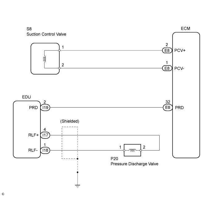
WIRING DIAGRAM
INSPECTION PROCEDURE
Tech Tips
Read freeze frame data using the intelligent tester. Freeze frame data records the engine condition when malfunctions are detected. When troubleshooting, freeze frame data can help determine if the vehicle was moving or stationary, if the engine was warmed up or not, and other data from the time the malfunction occurred.
PROCEDURE
-
CHECK OTHER DTC OUTPUT
-
Connect the intelligent tester to the DLC3.
-
Turn the ignition switch ON and turn the tester ON.
-
Enter the following menus: Powertrain / Engine and ECT / DTC.
-
Read the DTCs.
Result Display (DTC Output) Proceed to P1229 A P1229 and other DTCs B
B 
GO TO DTC CHART
A 
-
-
INSPECT SUPPLY PUMP ASSEMBLY (SUCTION CONTROL VALVE)
-
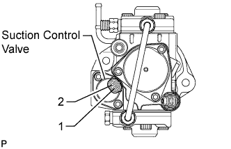
Disconnect the S8 suction control valve connector.
-
Measure the resistance of the suction control valve.
Standard resistance Tester Connection Condition Specified Condition 1 - 2 20°C (68°F) 1.9 to 2.3 Ω
NG
REPLACE SUPPLY PUMP ASSEMBLY (SUCTION CONTROL VALVE) Click here
OK
-
-
CHECK IF DTC OUTPUT RECURS (DTC P1229)
-
Connect the intelligent tester to the DLC3.
-
Turn the ignition switch ON and turn the tester ON.
-
Enter the following menus: Powertrain / Engine and ECT / DTC / Clear.
-
Clear the DTCs.
-
Disconnect the suction control valve connector and then start the engine. Wait for 1 minute.
Tech Tips
If the engine does not start, the suction control valve is normal. Therefore proceed to procedure 4.
-
Enter the following menus: Powertrain / Engine and ECT / DTC.
-
Read the DTCs.
Result Display (DTC Output) Proceed to P1229 not output A P1229 B
B
REPLACE SUPPLY PUMP ASSEMBLY (SUCTION CONTROL VALVE) Click here
A
-
-
CHECK HARNESS AND CONNECTOR (SUCTION CONTROL VALVE - ECM [PROCEDURE 4])
-
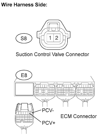
Disconnect the S8 suction control valve connector.
-
Disconnect the E8 ECM connector.
-
Measure the resistance of the wire harness side connector.
Standard resistance (Check for open) Tester Connection Specified Condition S8-1 - PCV+ (E8-2) Below 1 Ω S8-2 - PCV- (E8-1) Standard resistance (Check for short) Tester Connection Specified Condition S8-1 or PCV+ (E8-2) - Body ground 10 kΩ or higher S8-2 or PCV- (E8-1) - Body ground
NG
REPAIR OR REPLACE HARNESS OR CONNECTOR
OK
-
-
INSPECT ECM (PCV VOLTAGE)
-
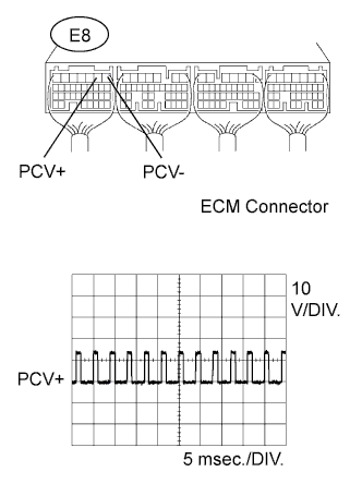
Inspect using the oscilloscope.
-
During cranking or idling, check the waveform between the specified terminals of the E8 ECM connector.
Standard Tester Connection Specified Condition PCV+ (E8-2) - PCV- (E8-1) Correct waveform is as shown
NG
REPLACE ECM Click here
OK
-
-
CHECK IF DTCS OUTPUT RECUR
Tech Tips
After clearing the DTC(s), drive the vehicle at 50 km/h (31 mph) for 5 minutes, and then confirm that DTC P1229 is not present again.
NEXT 
END