FRONT AIR CONDITIONING UNIT INSTALLATION
CAUTION / NOTICE / HINT
Tech Tips
-
Use the same procedure for RHD and LHD vehicles.
-
The procedure listed below is for LHD vehicles.
-
A bolt without a torque specification is shown in the standard bolt chart.
PROCEDURE
-
PRECAUTION
Note
-
When installing the instrument panel reinforcement with air conditioner assembly, make sure to replace the No. 1 instrument panel spacer with a new one.
-
The part number for the No. 1 instrument panel spacer varies according to the installation position, either on the vehicle side or on the instrument panel reinforcement assembly side. Therefore, make sure to check before installing it.
-
If it is necessary to replace the instrument panel extension spacer, use a new one of the same color as that which was removed.
-
-
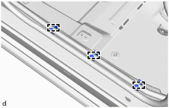
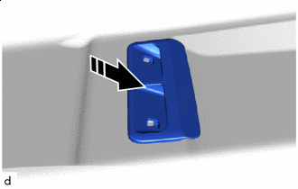
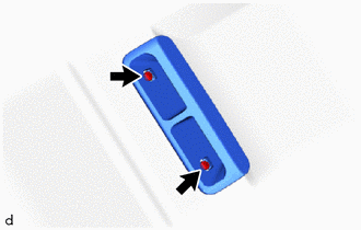
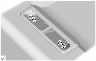
INSTALL NO. 1 INSTRUMENT PANEL SPACER
-
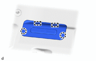
Attach the claw to install the 2 new No. 1 instrument panel spacers to the instrument panel reinforcement assembly.
-
Attach the claw to install a new No. 1 instrument panel spacers to the vehicle body.
-
-
INSTALL AIR CONDITIONER UNIT ASSEMBLY
Note
-
Be sure to support the air conditioner unit assembly when installing it because failure to do so may cause the bracket of the air conditioner unit assembly to break.
-
When installing the air conditioner unit assembly, eliminate static electricity by touching the vehicle body to prevent the components from being damaged.
-
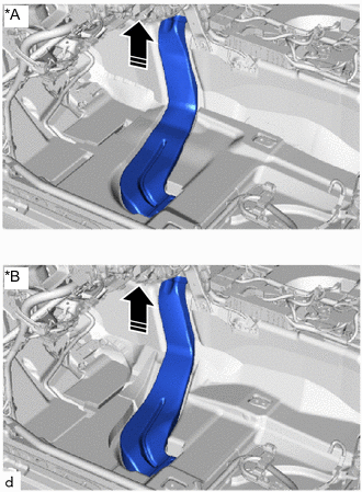
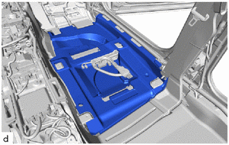
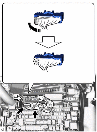
Temporarily set the air conditioner unit assembly nearby the position where it is to be installed.
-
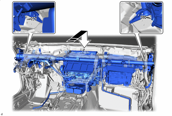
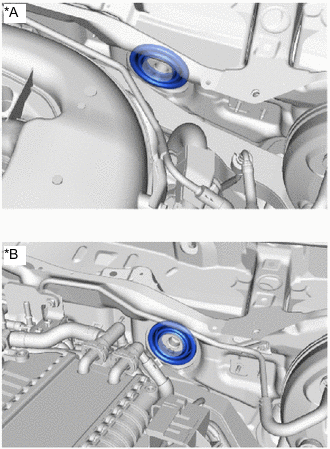
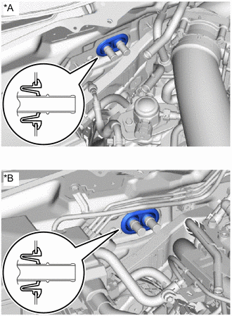
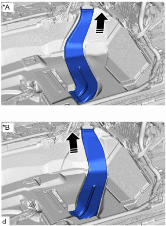
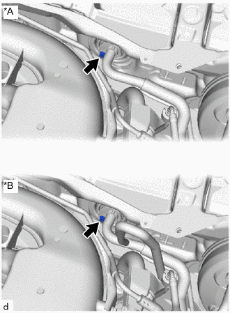
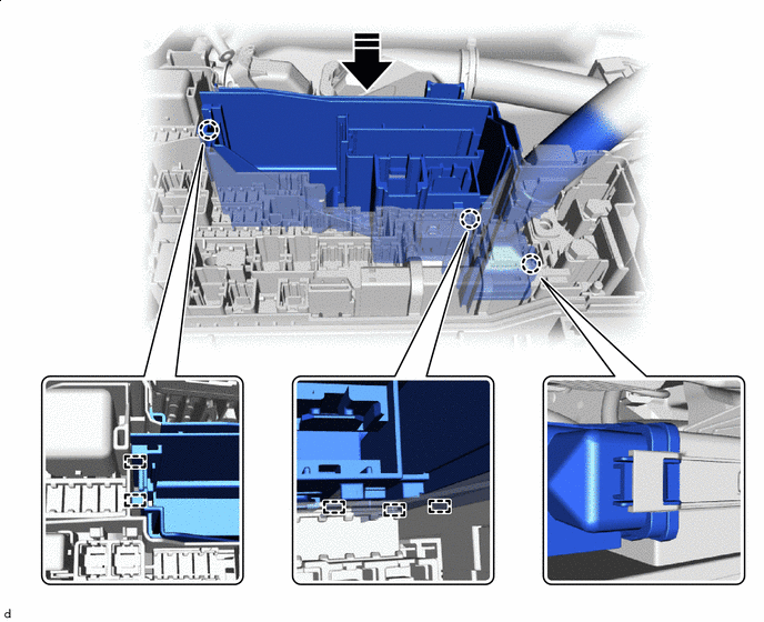
Insert the instrument panel reinforcement assembly into the application area of the air conditioner unit assembly as shown in the illustration.
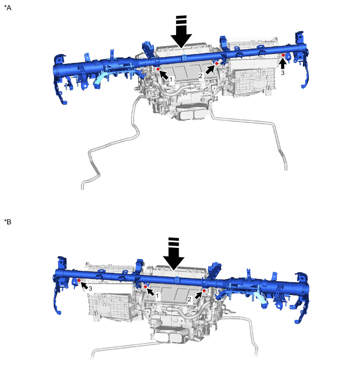
*A for LHD *B for RHD 
Install in this Direction - - -
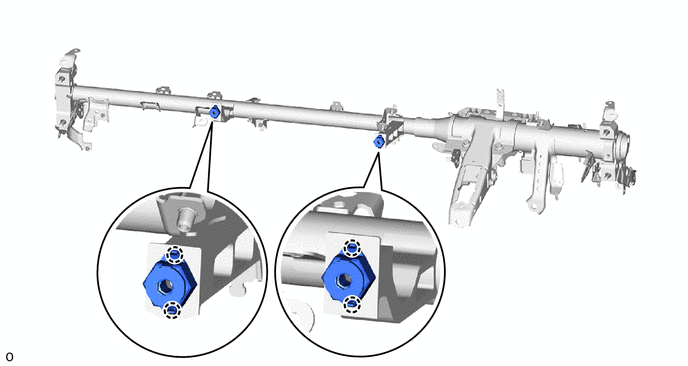
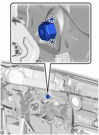
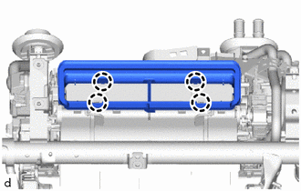
Install the 3 bolts in the order shown in the illustration.
- Torque:
- 9.8 N*m { 100 kgf*cm, 87 in.*lbf }
-
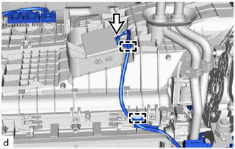
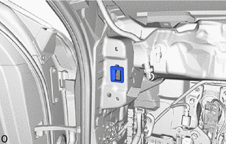
Attach the clamp.
-
Connect the connector.
-
-
INSTALL LOWER DEFROSTER NOZZLE ASSEMBLY
-
Attach the claw to install the lower defroster nozzle assembly.
-
-
INSTALL INSTRUMENT PANEL REINFORCEMENT ASSEMBLY WITH AIR CONDITIONING UNIT ASSEMBLY
Note
-
Be sure to support the air conditioning unit assembly when installing it because failure to do so may cause the bracket of the air conditioning unit assembly to break.
-
When installing the air conditioning unit assembly, eliminate static electricity by touching the vehicle body to prevent the components from being damaged.
-
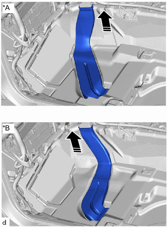
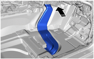
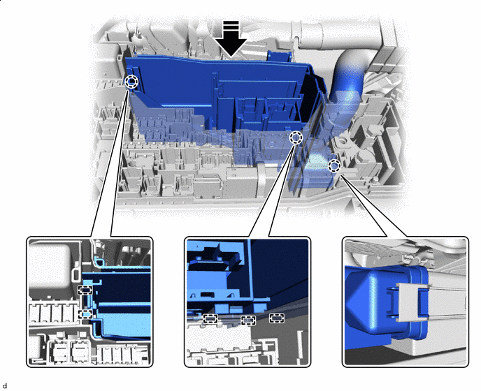
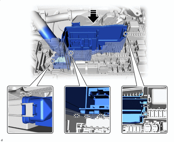
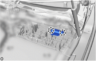
Install the instrument panel reinforcement assembly with air conditioning unit assembly to the guide as shown in the illustration.
Note
-
Be careful not to damage the internal components of the instrument panel reinforcement assembly and air conditioning unit assembly on the glass etc. Only perform installation after first taking the appropriate actions.
-
Make sure that both parts are securely installed to the guide.
-
Be sure to hold the air conditioning unit assembly by the case when carrying it.(Do not carry the air conditioning unit by holding the heater pipe, cooler pipe, servo motor, brushless motor, harness, air inlet door or link.)
-
Do not subject the air conditioning harness assembly connector to any strong impacts.
After inserting it to the end, install the guide - - -
-
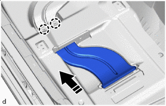
*A for 8GR-FKS *B for V35A-FTS Install the cooler pipe grommet.
Note
Make sure that the dash panel is securely inserted into the groove of the cooler pipe grommet without any gaps.
-
*A for 8GR-FKS *B for V35A-FTS Install the heater pipe grommet.
Note
Make sure that the dash panel is securely inserted into the groove of the heater pipe grommet without any gaps.
-
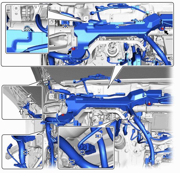
Temporarily install the 4 bolts (D).
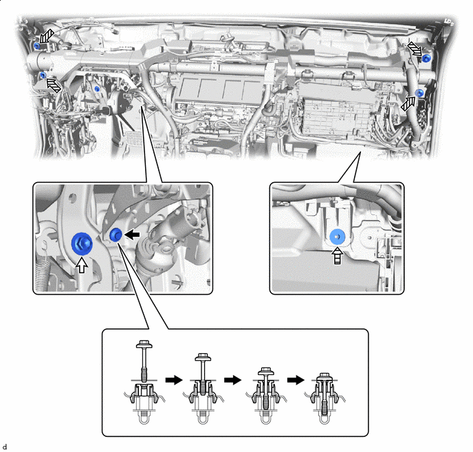

Bolt (B) 
Bolt (C) 
Bolt (D) Nut -
Temporarily install the bolt (C).
-
Using a universal socket wrench 12 mm, temporarily install the bolt (B).
-
for 8GR-FKS:
-
Using a universal socket wrench 12 mm, temporarily install the 2 bolts (A).
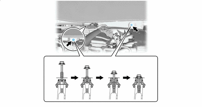
Bolt (A) - -
-
-
for V35A-FTS:
-
Using a universal socket wrench 12 mm, temporarily install the 2 bolts (A).
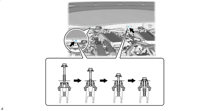
Bolt (A) - -
-
-
Temporarily install the nut.
-
Tighten the 4 bolts (D).
- Torque:
- 36 N*m { 367 kgf*cm, 27 ft.*lbf }
-
Using a universal socket wrench 12 mm, tighten the bolt (B) and 2 bolts (A).
- Torque:
- 20 N*m { 204 kgf*cm, 15 ft.*lbf }
-
Tighten the bolt (C).
- Torque:
- 15 N*m { 153 kgf*cm, 11 ft.*lbf }
-
Tighten the nut.
- Torque:
- 9.8 N*m { 100 kgf*cm, 87 in.*lbf }
-
-
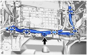
INSTALL DRAIN COOLER HOSE (for Front Passenger Side)
-
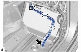
Install the drain cooler hose (for front passenger side).
-
Attach the guide.
-
-
INSTALL DRAIN COOLER HOSE (for Driver's Side)
-
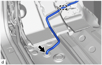
Install the drain cooler hose (for driver's side).
-
Attach the guide.
-
-
INSTALL NO. 3 HEATER TO REGISTER DUCT
-
Screw Clip Install the No. 3 heater to register duct with the 2 clips.
-
Install the screw.
-
-
INSTALL NO. 2 HEATER TO REGISTER DUCT
-
Install the No. 2 heater to register duct with the 3 clips.
-
-
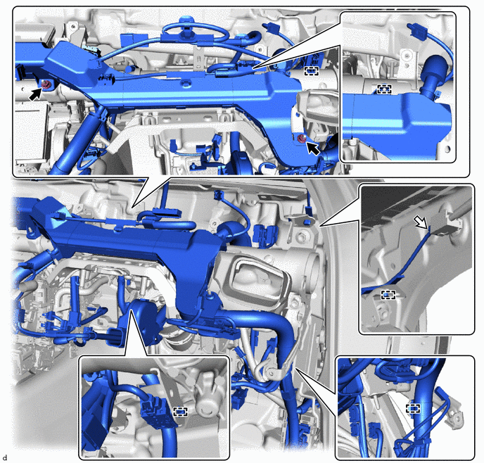
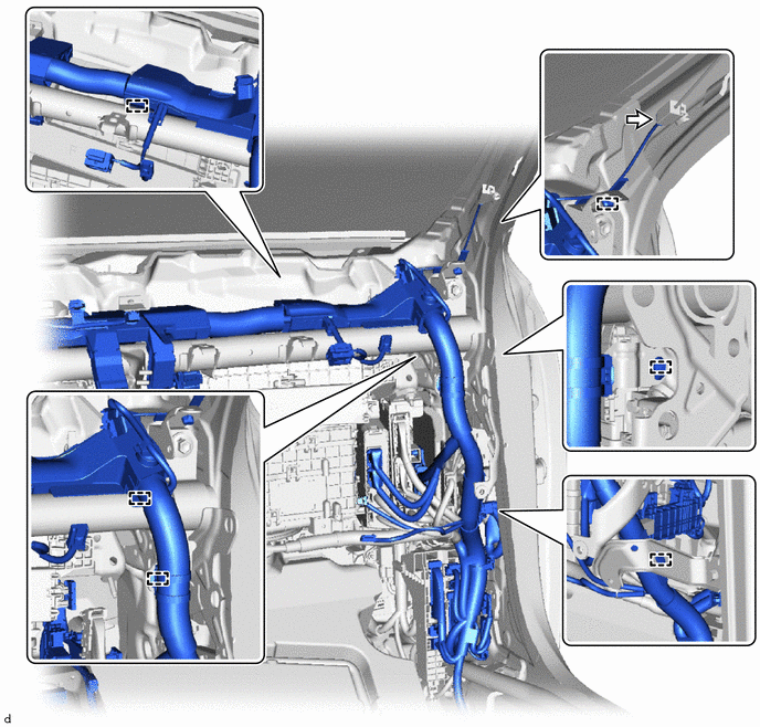
INSTALL INSTRUMENT PANEL WIRE (for LHD)
-
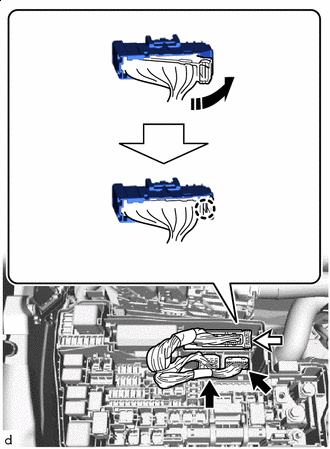
Lock in this Direction w/ VGRS:
-
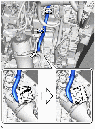
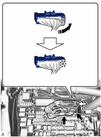
Connect the connector and move the lock as shown in the illustration.
Note
Be sure to connect the lever connector securely.
-
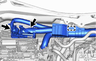
Attach the clamp.
-
-
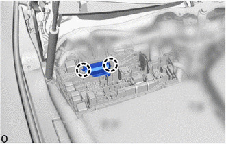
Attach the clamp.
-
Connect the 3 connectors.
-
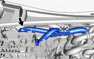
Install the 2 nuts.
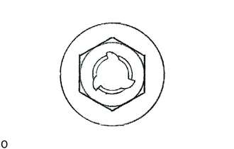
Note
If the removed nut is the same shape as that shown in the illustration, replace it the supplied replacement part.
- Torque:
- 8.0 N*m { 82 kgf*cm, 71 in.*lbf }
-
-
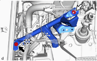
INSTALL INSTRUMENT PANEL WIRE (for RHD)
-
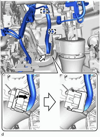
Lock in this Direction w/ VGRS:
-
Connect the connector and move the lock as shown in the illustration.
Note
Be sure to connect the lever connector securely.
-
Attach the clamp.
-
-
Attach the clamp.
-
Connect the connector.
-
Install the 2 nuts.
Note
If the removed nut is the same shape as that shown in the illustration, replace it the supplied replacement part.
- Torque:
- 8.0 N*m { 82 kgf*cm, 71 in.*lbf }
-
-
INSTALL AIR CONDITIONING AMPLIFIER ASSEMBLY
-
INSTALL INSTRUMENT PANEL JUNCTION BLOCK ASSEMBLY WITH MAIN BODY ECU
-
INSTALL NO. 3 INSTRUMENT PANEL TO COWL BRACE SUB-ASSEMBLY
-
Bolt Nut Install the No. 3 instrument panel to cowl brace sub-assembly with the bolt and nut.
- Torque:
- Bolt
- 10 N*m { 102 kgf*cm, 7 ft.*lbf }
- Nut
- 6.0 N*m { 61 kgf*cm, 53 in.*lbf }
-
Attach the clamp.
-
-
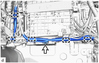
INSTALL INSTRUMENT PANEL WIRE
-
for LHD:
-
Attach the clamp.
-
Connect the 2 connectors.
Tech Tips
The 2 connectors can be connected in any position (top or bottom).
-
-
for RHD:
-
Attach the clamp.
-
Connect the 2 connectors.
Tech Tips
The 2 connectors can be connected in any position (top or bottom).
-
-
-
INSTALL NO. 1 INSTRUMENT PANEL BRACE SUB-ASSEMBLY (for LHD)
-
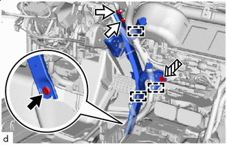
Bolt Nut Screw Install the No. 1 instrument panel brace sub-assembly with the bolt and 2 nuts.
- Torque:
- Bolt
- 20 N*m { 204 kgf*cm, 15 ft.*lbf }
- Nut
- 18 N*m { 184 kgf*cm, 13 ft.*lbf }
-
Install the screw.
-
Attach the clamp.
-
-
INSTALL NO. 2 INSTRUMENT PANEL BRACE SUB-ASSEMBLY (for LHD)
-
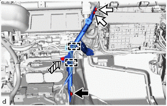
Bolt Nut Screw Install the No. 2 instrument panel brace sub-assembly with the bolt and 2 nuts.
Note
If the removed nut is the same shape as that shown in the illustration, replace it the supplied replacement part.
- Torque:
- Bolt
- 20 N*m { 204 kgf*cm, 15 ft.*lbf }
- Nut
- 6.0 N*m { 61 kgf*cm, 53 in.*lbf }
-
Install the screw.
-
Attach the clamp.
-
-
INSTALL NO. 2 INSTRUMENT PANEL BRACE SUB-ASSEMBLY (for RHD)
-
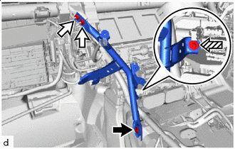
Bolt Nut Screw Install the No. 2 instrument panel brace sub-assembly with the bolt and 2 nuts.
Note
If the removed nut is the same shape as that shown in the illustration, replace it the supplied replacement part.
- Torque:
- Bolt
- 20 N*m { 204 kgf*cm, 15 ft.*lbf }
- Nut
- 6.0 N*m { 61 kgf*cm, 53 in.*lbf }
-
Install the screw.
-
-
INSTALL NO. 1 INSTRUMENT PANEL BRACE SUB-ASSEMBLY (for RHD)
-
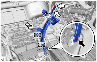
Bolt Nut Screw Install the No. 1 instrument panel brace sub-assembly with the bolt and 2 nuts.
- Torque:
- Bolt
- 20 N*m { 204 kgf*cm, 15 ft.*lbf }
- Nut
- 18 N*m { 184 kgf*cm, 13 ft.*lbf }
-
Install the screw.
-
Attach the clamp.
-
-
INSTALL WIRING HARNESS CLAMP BRACKET
-
Install the wiring harness clamp bracket with the screw.
-
-
INSTALL PASSENGER SIDE JUNCTION BLOCK ASSEMBLY WITH NETWORK GATEWAY ECU
-
INSTALL FRONT STEERING CONTROL ECU (w/ VGRS)
-
INSTALL ENGINE STOP AND START ECU (w/ Stop and Start System)
-
for LHD:
-
for RHD:
-
-
INSTALL SHIFT CONTROL ECU
-
for 2WD:
-
for AWD:
-
-
INSTALL NO. 2 SEMICONDUCTOR POWER INTEGRATION ECU (w/ PTC Heater)
-
INSTALL SEMICONDUCTOR POWER INTEGRATION ECU (w/o PTC Heater)
Tech Tips
Use the same procedure as for the No. 2 semiconductor power integration ECU.
-
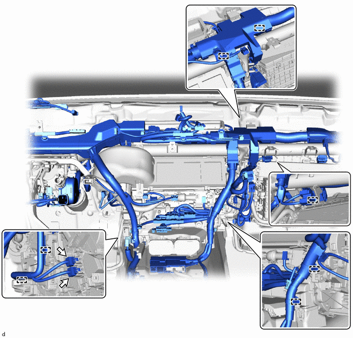
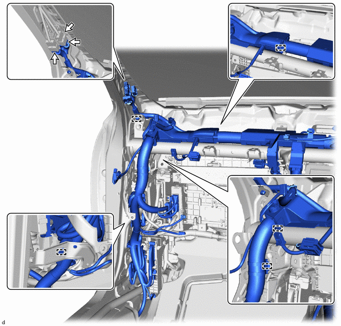
INSTALL INSTRUMENT PANEL WIRE
-
for LHD:
-
Attach the clamp.
-
Connect the connector.
-
Connect the connector.
-
Attach the clamp.
-
-
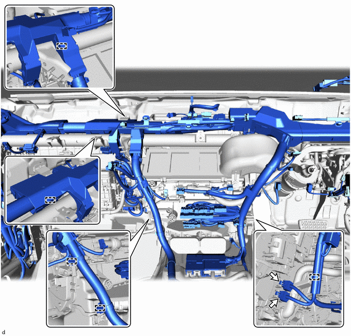
for RHD:
-
Attach the clamp.
-
Connect the 3 connectors.
-
Connect the connector.
-
Attach the clamp.
-
-
-
INSTALL NO. 2 AIR DUCT SUB-ASSEMBLY
-
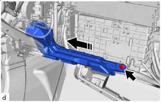
Install in this Direction Install the No. 2 air duct sub-assembly with the clip.
-
-
INSTALL FRONT FLOOR MAT LH
-
for LHD:
-
Install the front floor mat LH.
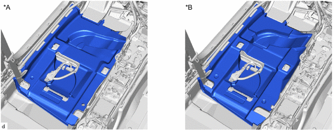
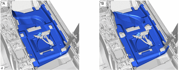
*A for 2WD *B for AWD
-
-
for RHD:
-
Install the front floor mat LH.
*A for Rear Power Seat with Ottoman *B except Rear Power Seat with Ottoman
-
-
-
INSTALL REAR NO. 2 AIR DUCT
-
for LHD:
-
*A for 2WD *B for AWD Install in this Direction Install the rear No. 2 air duct.
-
-
for RHD:
-
*A for Rear Power Seat with Ottoman *B except Rear Power Seat with Ottoman Install in this Direction Install the rear No. 2 air duct.
-
-
-
INSTALL REAR AIR DUCT GUIDE LH
-
Install in this Direction Attach the claw and install the rear air duct guide LH.
-
-
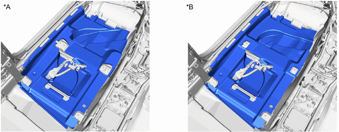
INSTALL FRONT FLOOR MAT RH
-
for LHD:
-
Install the front floor mat RH.
*A except Rear Power Seat with Ottoman *B for Rear Power Seat with Ottoman
-
-
for RHD:
-
Install the front floor mat RH.
-
-
-
INSTALL REAR NO. 1 AIR DUCT
-
for LHD:
-
*A except Rear Power Seat with Ottoman *B for Rear Power Seat with Ottoman Install in this Direction Install the rear No. 1 air duct.
-
-
for RHD:
-
Install in this Direction Install the rear No. 1 air duct.
-
-
-
INSTALL REAR AIR DUCT GUIDE RH
Tech Tips
Use the same procedure as for the rear air duct guide LH.
-
INSTALL FRONT FLOOR CARPET ASSEMBLY FRONT
-
for LHD:
-
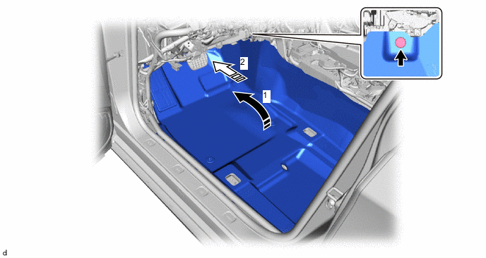
Install the front floor carpet assembly front in the order shown in the illustration.
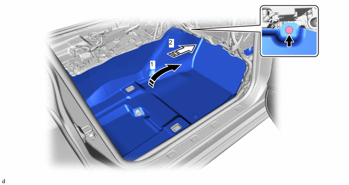
Install in this Direction 
Insert to the end -
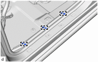
Install the clip.
-
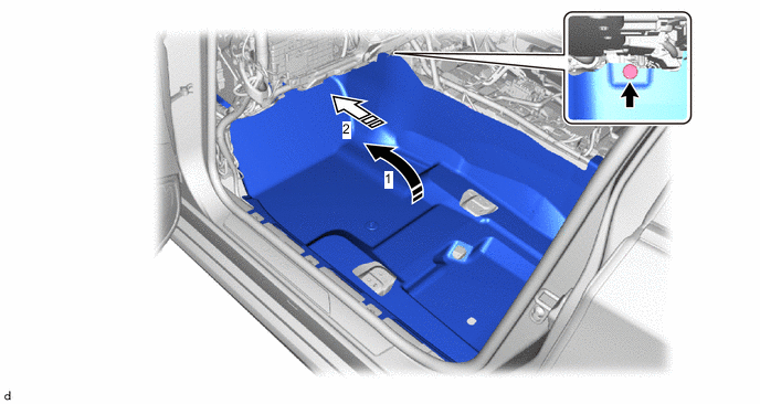
Install the front floor carpet assembly front in the order shown in the illustration.
Install in this Direction Insert to the end -
Install the clip.
-
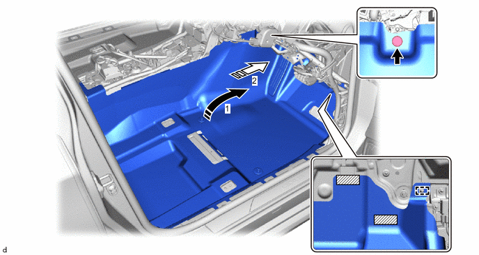
Attach the clamp.
Tech Tips
Use the same procedure for the opposite side.
-
-
for RHD:
-
Install the front floor carpet assembly front in the order shown in the illustration.
Install in this Direction Insert to the end -
Install the clip.
-
Install the front floor carpet assembly front in the order shown in the illustration.
Install in this Direction Insert to the end 
Fastener - - -
Attach each fastener and guide.
-
Install the clip.
-
Attach the clamp.
Tech Tips
Use the same procedure for the opposite side.
-
-
-
INSTALL REAR NO. 3 AIR DUCT
-
Install in this Direction Install the rear No. 3 air duct in the direction of the arrow shown in the illustration.
Tech Tips
Use the same procedure for both rear No. 3 air ducts.
-
Install the 2 screws.
Tech Tips
Use the same procedure for the opposite side.
-
-
INSTALL AIR DUCT PLUG
-
Attach the claw to install the 2 air duct plugs.
Tech Tips
Use the same procedure for the opposite side.
-
-
INSTALL FRONT FLOOR CAUTION PLATE COVER
-
Attach the claw and guide to install the front floor caution plate cover.
-
-
INSTALL ACCELERATOR PEDAL
-
for 8GR-FKS:
-
for V35A-FTS:
-
-
INSTALL ACCELERATOR PEDAL PAD
-
for 8GR-FKS:
-
for V35A-FTS:
-
-
INSTALL LOWER CENTER PILLAR GARNISH LH
-
INSTALL REAR DOOR SCUFF PLATE LH
-
INSTALL LOWER CENTER PILLAR GARNISH RH
Tech Tips
Use the same procedure described for the lower center pillar garnish LH.
-
INSTALL REAR DOOR SCUFF PLATE RH
Tech Tips
Use the same procedure described for the rear door scuff plate LH.
-
CONNECT AIR CONDITIONING TUBE AND ACCESSORY ASSEMBLY (for 8GR-FKS)
-
Remove the vinyl tape wrapped around the connection of the air conditioning tube and accessory assembly and the air conditioning tube and accessory assembly.
-
Sufficiently apply compressor oil to 2 new O-rings and the fitting surface of the air conditioning tube and accessory assembly.
Compressor Oil Refrigerant Compressor Oil HFC-134a (R134a) ND-OIL 8 or equivalent HFO-1234yf (R1234yf) ND-OIL 12 or equivalent -
Install the 2 O-rings to the air conditioning tube and accessory assembly.
Note
Keep the O-ring and O-ring fitting surface free of foreign matter.
-
Press in the air conditioning tube and accessory assembly until the shaft center of the pipe joint securely engages the seal hole.
Note
-
Do not apply excessive force to the air conditioning tube and accessory assembly.
-
Make sure not to cut the O-ring while installing it. (Cut O-rings cannot be installed)
-
-
w/o Rear Cooler:
-
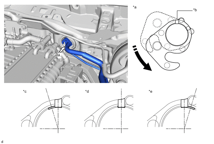
Rotate the 1-point tightening plate and align the 1-point tightening plate of air conditioning tube and accessory assembly with the tube marking (black).
Note
Make sure that the air conditioning tube and accessory assembly 1-point tightening plate is partially on the marking
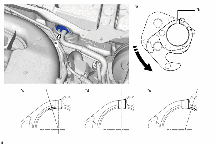
*a View A *b Air Conditioning Tube and Accessory Assembly 1-Point Tightening Plate Marking *c Counterclockwise (OK) *d Standard *e Clockwise (OK) - - Rotate in this Direction Air Conditioning Tube and Accessory Assembly Marking
-
-
w/ Rear Cooler:
-
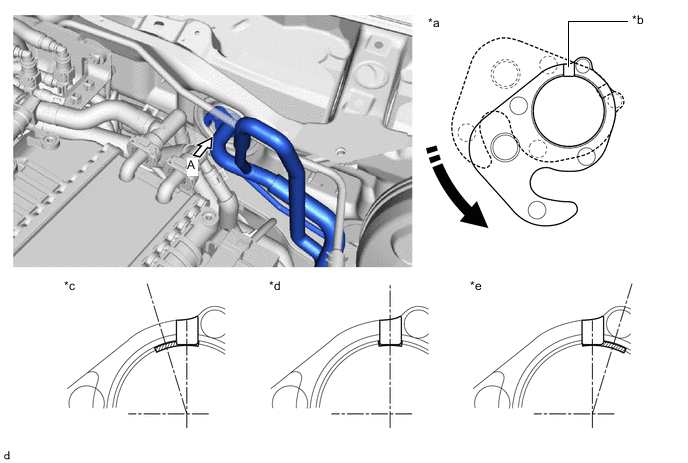
Rotate the 1-point tightening plate and align the 1-point tightening plate of air conditioning tube and accessory assembly with the tube marking (black).
Note
Make sure that the air conditioning tube and accessory assembly 1-point tightening plate is partially on the marking
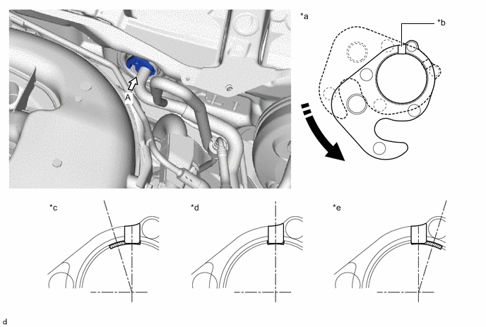
*a View A *b Air Conditioning Tube and Accessory Assembly 1-Point Tightening Plate Marking *c Counterclockwise (OK) *d Standard *e Clockwise (OK) - - Rotate in this Direction Air Conditioning Tube and Accessory Assembly Marking
-
-
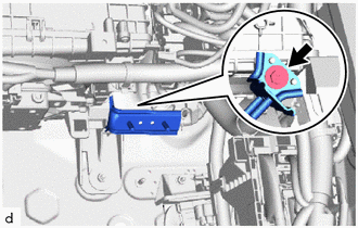
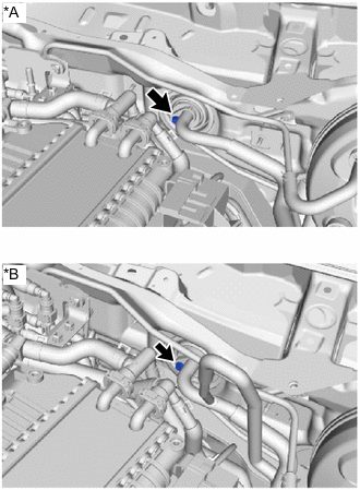
*A w/o Rear Cooler *B w/ Rear Cooler Install the bolt.
- Torque:
- 9.8 N*m { 100 kgf*cm, 87 in.*lbf }
-
-
CONNECT AIR CONDITIONING TUBE AND ACCESSORY ASSEMBLY (for V35A-FTS)
-
Remove the vinyl tape wrapped around the connection of the air conditioning tube and accessory assembly and the air conditioning tube and accessory assembly.
-
Sufficiently apply compressor oil to 2 new O-rings and the fitting surface of the air conditioning tube and accessory assembly.
Compressor Oil Refrigerant Compressor Oil HFC-134a (R134a) ND-OIL 8 or equivalent HFO-1234yf (R1234yf) ND-OIL 12 or equivalent -
Install the 2 O-rings to the air conditioning tube and accessory assembly.
Note
Keep the O-ring and O-ring fitting surface free of foreign matter.
-
Press in the air conditioning tube and accessory assembly until the shaft center of the pipe joint securely engages the seal hole.
Note
-
Do not apply excessive force to the air conditioning tube and accessory assembly.
-
Make sure not to cut the O-ring while installing it. (Cut O-rings cannot be installed)
-
-
w/o Rear Cooler:
-
Rotate the 1-point tightening plate and align the 1-point tightening plate of air conditioning tube and accessory assembly with the tube marking (black).
Note
Make sure that the air conditioning tube and accessory assembly 1-point tightening plate is partially on the marking
*a View A *b Air Conditioning Tube and Accessory Assembly 1-Point Tightening Plate Marking *c Counterclockwise (OK) *d Standard *e Clockwise (OK) - - Rotate in this Direction Air Conditioning Tube and Accessory Assembly Marking
-
-
w/ Rear Cooler:
-
Rotate the 1-point tightening plate and align the 1-point tightening plate of air conditioning tube and accessory assembly with the tube marking (black).
Note
Make sure that the air conditioning tube and accessory assembly 1-point tightening plate is partially on the marking
*a View A *b Air Conditioning Tube and Accessory Assembly 1-Point Tightening Plate Marking *c Counterclockwise (OK) *d Standard *e Clockwise (OK) - - Rotate in this Direction Air Conditioning Tube and Accessory Assembly Marking
-
-
*A w/o Rear Cooler *B w/ Rear Cooler Install the bolt.
- Torque:
- 9.8 N*m { 100 kgf*cm, 87 in.*lbf }
-
-
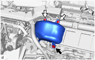
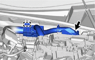
INSTALL INLET HEATER WATER HOSE (for 8GR-FKS)
-
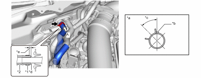
Install the inlet heater water hose as shown in the illustration.
Note
-
Do not apply excessive force to the inlet heater water hose.
-
Insert the inlet heater water hose until it contacts the stopper.
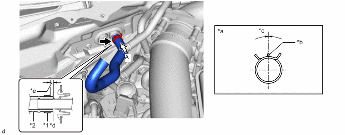
*1 Hose Clip *2 Inlet Heater Water Hose *a View A *b Marking (Green) *c Hose Clip Installation Angle (-15 to 15°) *d Stopper *e Hose Clip Installation Range (2 to 7 mm (0.0787 to 0.276 in.)) - - -
-
Make sure to install the hose clip within the range shown in the illustration.
-
-
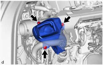
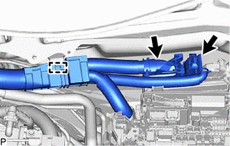
INSTALL OUTLET HEATER WATER HOSE (for 8GR-FKS)
-
Install the outlet heater water hose as shown in the illustration.
Note
-
Do not apply excessive force to the outlet heater water hose.
-
Insert the outlet heater water hose until it contacts the stopper.
*1 Hose Clip *2 Outlet Heater Water Hose *a View A *b Marking (Green) *c Hose Clip Installation Angle (30 to 60°) *d Stopper *e Hose Clip Installation Range (2 to 7 mm (0.0787 to 0.276 in.)) - - -
-
Make sure to install the hose clip within the range shown in the illustration.
-
-
CONNECT INLET HEATER WATER HOSE (for 8GR-FKS)
-
CONNECT OUTLET HEATER WATER HOSE (for 8GR-FKS)
-
INSTALL WATER HOSE SUB-ASSEMBLY (for V35A-FTS, Inlet Side)
-
Install the water hose sub-assembly as shown in the illustration.
Note
-
Do not apply excessive force to the water hose sub-assembly.
-
Make sure the water hose sub-assembly is securely inserted to the stopper. However, If the end of the water hose sub-assembly is cut diagonally, it is acceptable for the entire circumference of the tip to not contact the stopper.
-
The installation tolerance of the water hose sub-assembly rotation direction is within 1 paint mark width of the nominal position.
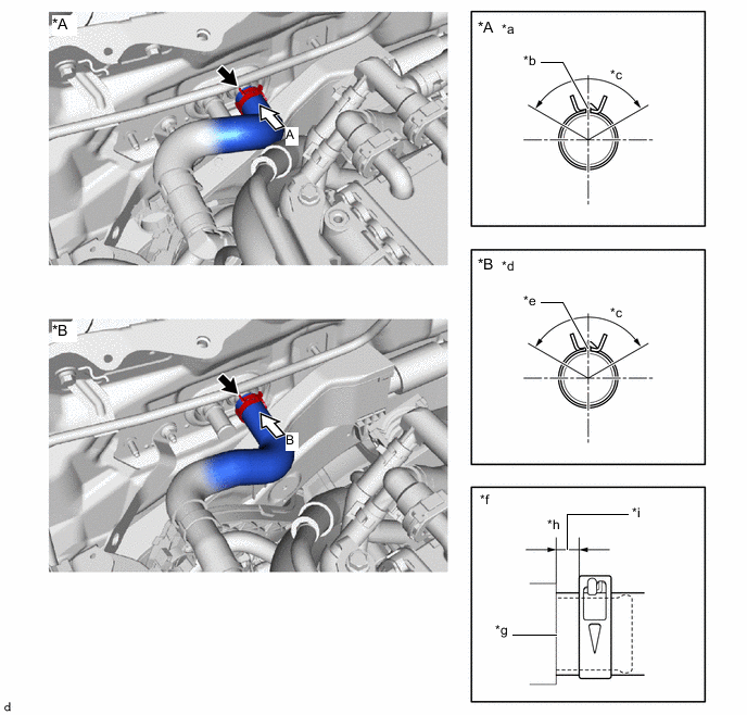
*A for 2WD *B for AWD *a View A *b for LHD: Marking (Red)
for RHD: Marking (Blue)
*c Hose Clip Installation Angle (120°) *d View B *e for LHD: Marking (Orange)
for RHD: Marking (Green)
*f Water Hose Sub-Assembly and Hose Clip Axial Direction Aligning Position *g Contact Position *h Water Hose Sub-Assembly and Hose End *i Hose Clip Installation Range (2 to 7 mm (0.0787 to 0.276 in.)) - - -
-
Make sure to install the hose clip within the range shown in the illustration.
-
-
INSTALL WATER HOSE SUB-ASSEMBLY (for V35A-FTS, Outlet Side)
-
Install the water hose sub-assembly as shown in the illustration.
Note
-
Do not apply excessive force to the water hose sub-assembly.
-
Make sure the water hose sub-assembly is securely inserted to the stopper. However, If the end of the water hose sub-assembly is cut diagonally, it is acceptable for the entire circumference of the tip to not contact the stopper.
-
The installation tolerance of the water hose sub-assembly rotation direction is within 1 paint mark width of the nominal position.
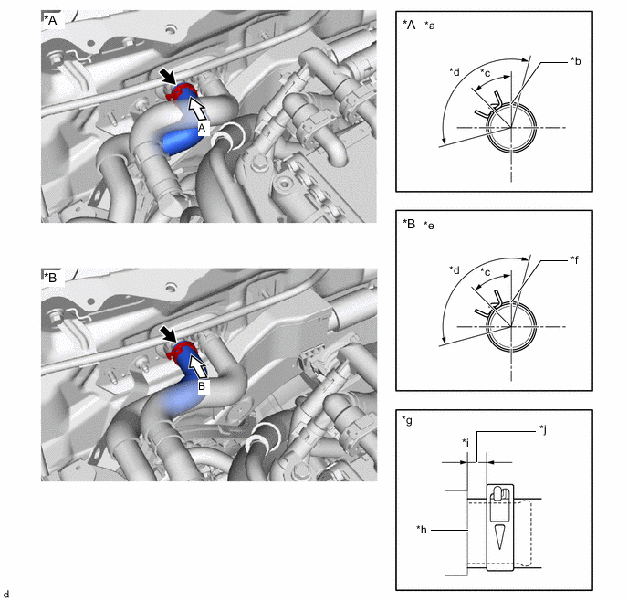
*A for 2WD *B for AWD *a View A *b for LHD: Marking (Red)
for RHD: Marking (Blue)
*c Hose Clip Installation Angle (45°) *d Hose Clip Installation Angle (120°) *e View B *f for LHD: Marking (Orange)
for RHD: Marking (Green)
*g Water Hose Sub-Assembly and Hose Clip Axial Direction Aligning Position *h Contact Position *i Water Hose Sub-Assembly and Hose End *j Hose Clip Installation Range (2 to 7 mm (0.0787 to 0.276 in.)) -
-
Install the water hose sub-assembly as shown in the illustration.
-
Attach the clamp.
Note
Make sure the marking is hidden in the clamp.
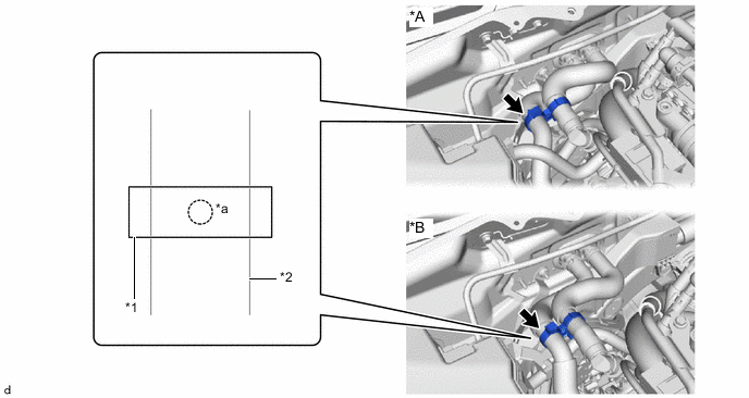
*A for 2WD *B for AWD *1 Clamp *2 Water Hose Sub-Assembly *a Marking - -
-
-
CONNECT WATER HOSE SUB-ASSEMBLY (for V35A-FTS, Inlet Side)
-
CONNECT WATER HOSE SUB-ASSEMBLY (for V35A-FTS, Outlet Side)
-
CONNECT NO. 14 CONNECTOR HOLDER
-
for 8GR-FKS, LHD:
-
Attach the guide, claw and connect the No. 14 connector holder to the No. 17 connector holder.
Connect in this Direction - - -
Connector Lever Connector Rotate in this Direction Attach the claw to connect the lever connector.
Note
Be sure to connect the lever connector securely.
-
Connect the 2 connectors.
-
Attach the claw to install the No. 1 semiconductor power integration ECU.
Note
-
Make sure the connector terminal is free from oil and grease.
-
Do not subject the No. 1 semiconductor power integration ECU to any impact.
-
Do not use a No. 1 semiconductor power integration ECU that has been dropped.
-
Do not disassemble the No. 1 semiconductor power integration ECU.
-
-
Connect the connector.
-
Attach the clamp.
-
-
for V35A-FTS, LHD:
-
Attach the guide, claw and connect the No. 14 connector holder to the No. 17 connector holder.
Connect in this Direction - - -
Connector Lever Connector Rotate in this Direction Attach the claw to connect the lever connector.
Note
Be sure to connect the lever connector securely.
-
Connect the 2 connectors.
-
Attach the claw to install the No. 1 semiconductor power integration ECU.
Note
-
Make sure the connector terminal is free from oil and grease.
-
Do not subject the No. 1 semiconductor power integration ECU to any impact.
-
Do not use a No. 1 semiconductor power integration ECU that has been dropped.
-
Do not disassemble the No. 1 semiconductor power integration ECU.
-
-
Connect the 2 connectors.
-
Attach the clamp.
-
-
for 8GR-FKS, RHD:
-
Attach the guide, claw and connect the No. 14 connector holder to the No. 17 connector holder.
Connect in this Direction - - -
Connector Lever Connector Rotate in this Direction Attach the claw to connect the lever connector.
Note
Be sure to connect the lever connector securely.
-
Connect the 2 connectors.
-
Attach the claw to install the No. 1 semiconductor power integration ECU.
Note
-
Make sure the connector terminal is free from oil and grease.
-
Do not subject the No. 1 semiconductor power integration ECU to any impact.
-
Do not use a No. 1 semiconductor power integration ECU that has been dropped.
-
Do not disassemble the No. 1 semiconductor power integration ECU.
-
-
Connect the connector.
-
Attach the clamp.
-
-
for V35A-FTS, RHD:
-
Attach the guide, claw and connect the No. 14 connector holder to the No. 17 connector holder.
Connect in this Direction - - -
Connector Lever Connector Rotate in this Direction Attach the claw to connect the lever connector.
Note
Be sure to connect the lever connector securely.
-
Connect the 2 connectors.
-
Attach the claw to install the No. 1 semiconductor power integration ECU.
Note
-
Make sure the connector terminal is free from oil and grease.
-
Do not subject the No. 1 semiconductor power integration ECU to any impact.
-
Do not use a No. 1 semiconductor power integration ECU that has been dropped.
-
Do not disassemble the No. 1 semiconductor power integration ECU.
-
-
Connect the 2 connectors.
-
Attach the clamp.
-
-
-
INSTALL NO. 1 RELAY BLOCK COVER
-
for LHD:
-
for RHD:
-
-
INSTALL FENDER APRON BRACE SUB-ASSEMBLY LH (for 8GR-FKS)
-
INSTALL FENDER APRON BRACE SUB-ASSEMBLY RH (for 8GR-FKS)
-
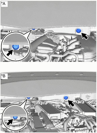
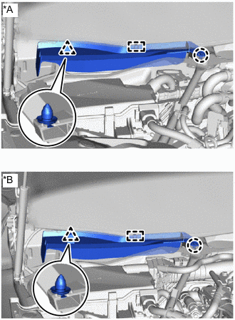
INSTALL FENDER APRON BRACE SUB-ASSEMBLY LH (for V35A-FTS)
-
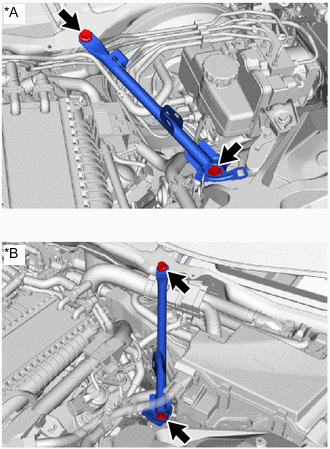
*A for LHD *B for RHD Install the fender apron brace sub-assembly LH with the 2 bolts.
- Torque:
- 49 N*m { 500 kgf*cm, 36 ft.*lbf }
-
for RHD:
-
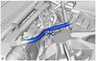
Attach the clamp.
-
-
-
INSTALL FENDER APRON BRACE SUB-ASSEMBLY RH (for V35A-FTS)
-
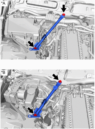
*A for LHD *B for RHD Install the fender apron brace sub-assembly RH with the 2 bolts.
- Torque:
- 49 N*m { 500 kgf*cm, 36 ft.*lbf }
-
for LHD:
-
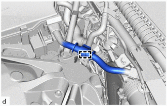
Attach the clamp.
-
-
-
INSTALL HOLE PLUG
-
*A for 8GR-FKS *B for V35A-FTS Install the 2 hole plugs.
-
-
INSTALL COWL VENTILATOR SPLASH SHIELD RH (for LHD)
-
*A for 8GR-FKS *B for V35A-FTS Attach the claw.
-
Attach the guide and clip to install the cowl ventilator splash shield RH.
-
-
INSTALL COWL VENTILATOR SPLASH SHIELD LH (for RHD)
Tech Tips
Use the same procedure as for the cowl ventilator splash shield RH.
-
INSTALL FRONT WIPER MOTOR AND LINK
-
INSTALL HEADUP DISPLAY (w/ Headup Display)
-
INSTALL STEERING COLUMN ASSEMBLY
-
INSTALL INSTRUMENT PANEL SAFETY PAD SUB-ASSEMBLY
-
INSTALL FRONT SEAT ASSEMBLY LH
-
INSTALL FRONT SEAT ASSEMBLY RH
Tech Tips
Use the same procedure as for the front seat assembly LH.
-
CONNECT CABLE TO NEGATIVE BATTERY TERMINAL
-
for 8GR-FKS:
-
for V35A-FTS:
-
-
INSTALL LUGGAGE COMPARTMENT MAT SUB-ASSEMBLY
-
CHARGE AIR CONDITIONING SYSTEM WITH REFRIGERANT
-
for HFC-134a(R134a):
-
for HFO-1234yf(R1234yf):
-
-
ADD ENGINE COOLANT
-
for 8GR-FKS:
-
for V35A-FTS:
-
-
INSPECT FOR COOLANT LEAK
-
for 8GR-FKS:
-
for V35A-FTS:
-
-
WARM UP ENGINE
-
for HFC-134a(R134a):
-
for HFO-1234yf(R1234yf):
-
-
INSPECT FOR REFRIGERANT LEAK
-
for HFC-134a(R134a):
-
for HFO-1234yf(R1234yf):
-
-
INSTALL NO. 2 ENGINE UNDER COVER ASSEMBLY (for 8GR-FKS)
-
INSTALL TRANSMISSION UNDER COVER (for 8GR-FKS)
-
INSTALL NO. 1 ENGINE UNDER COVER ASSEMBLY (for 8GR-FKS)
-
INSTALL OIL PAN PROTECTOR (for V35A-FTS 2WD)
-
INSTALL ENGINE UNDER COVER BRACKET RH (for V35A-FTS AWD)
-
CONNECT NO. 1 ENGINE UNDER COVER ASSEMBLY (for V35A-FTS)
-
INSTALL LOWER RADIATOR AIR DEFLECTOR
-
INSTALL UPPER RADIATOR SUPPORT SEAL
-
INSTALL RADIATOR COVER PLATE
-
INSTALL V-BANK COVER SUB-ASSEMBLY (for 8GR-FKS)
-
INSTALL V-BANK COVER SUB-ASSEMBLY (for V35A-FTS)
-
CHECK AND CLEAR DTC
-
for 8GR-FKS:
-
for V35A-FTS 2WD:
-
for V35A-FTS AWD:
-