MONOLITHIC CONVERTER INSTALLATION
PROCEDURE
-
INSTALL STUD BOLT
Tech Tips
If a stud bolt is deformed or its threads are damaged, replace it.
-
Using an E10 "TORX" socket wrench, install the 2 stud bolts to the exhaust manifold converter sub-assembly (TWC: Front Catalyst).
- Torque:
- 14.5 N*m { 148 kgf*cm, 11 ft.*lbf }
-
-
INSTALL EXHAUST MANIFOLD CONVERTER SUB-ASSEMBLY (TWC: Front Catalyst)
-
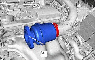
Set a new exhaust pipe clamp to the turbocharger sub-assembly.
Note
Do not open the exhaust pipe clamp more than 140 mm (5.51 in.). The standard required opening should be approximately 60 mm (2.36 in.).
-
Temporarily install the turbocharger stay to the exhaust manifold converter sub-assembly (TWC: Front Catalyst) with the nut.
Note
Tighten the nut by hand until it contacts the surface of the turbocharger stay.
-
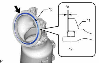
*1 Exhaust Manifold Converter Sub-assembly (TWC: Front Catalyst) *2 Outlet Turbine Elbow Gasket *a 1.5 mm (0.0591 in.) or less *b Knock Pin Install a new outlet turbine elbow gasket to the exhaust manifold converter sub-assembly (TWC: Front Catalyst) as shown in the illustration.
Note
When reusing the exhaust manifold converter sub-assembly (TWC: Front Catalyst), thoroughly clean the gasket groove.
Tech Tips
Make sure that the outlet turbine elbow gasket is securely installed into the gasket groove of the exhaust manifold converter sub-assembly (TWC: Front Catalyst).
-
Temporarily install the turbocharger stay to the stud bolt on the cylinder head sub-assembly side with the nut.
Note
Tighten the nut by hand until it contacts the surface of the turbocharger stay.
-
While aligning the knock pin of the exhaust manifold converter sub-assembly (TWC: Front Catalyst) with the pin hole on the turbocharger sub-assembly, set the exhaust manifold converter sub-assembly (TWC: Front Catalyst) to the turbocharger sub-assembly.
-
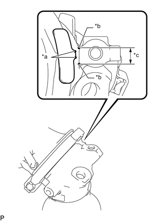
*a Protrusion on Exhaust Pipe Clamp Side *b Protrusion on Exhaust Manifold Converter Sub-assembly (TWC: Front Catalyst) Side *c Alignment Area While aligning the protrusion of the exhaust pipe clamp as shown in the illustration, temporarily install the exhaust pipe clamp.
-
Temporarily install the manifold stay with the bolt and nut.
-
Tighten the exhaust pipe clamp.
- Torque:
- 23 N*m { 235 kgf*cm, 17 ft.*lbf }
-
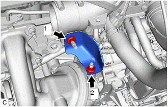
Tighten the 2 nuts in the order shown in the illustration.
- Torque:
- 43 N*m { 438 kgf*cm, 32 ft.*lbf }
-
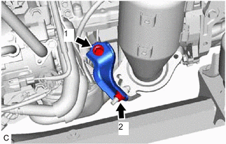
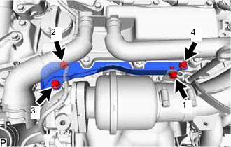
Tighten the bolt and nut in the order shown in the illustration.
- Torque:
- 43 N*m { 438 kgf*cm, 32 ft.*lbf }
-
-
INSTALL NO. 2 EXHAUST MANIFOLD HEAT INSULATOR
-
Install the No. 2 exhaust manifold heat insulator to the exhaust manifold converter sub-assembly (TWC: Front Catalyst) with the 4 bolts.
- Torque:
- 13.5 N*m { 138 kgf*cm, 10 ft.*lbf }
-
-
INSTALL NO. 1 EXHAUST MANIFOLD HEAT INSULATOR
-
Install the No. 1 exhaust manifold heat insulator to the cylinder head sub-assembly and exhaust manifold converter sub-assembly (TWC: Front Catalyst) with the 3 bolts.
- Torque:
- 15 N*m { 153 kgf*cm, 11 ft.*lbf }
-
-
INSTALL AIR FUEL RATIO SENSOR
-
INSTALL INTAKE AIR RESONATOR
-
*a Gasket Groove Install the intake air resonator to the No. 1 air hose with the hose clamp shown in the illustration.
Tech Tips
-
Install the intake air resonator so that the gasket groove is visible from the front.
-
Tighten the hose clamp after installing the outlet compressor elbow.
-
-
-
INSTALL OUTLET COMPRESSOR ELBOW
-
Install a new air tube gasket to the intake air resonator.
-
Install a new outlet compressor gasket to the turbocharger sub-assembly.
-
Install the outlet compressor elbow to the intake air resonator and turbocharger sub-assembly with the 3 bolts and 2 nuts.
- Torque:
- Bolt
- 10 N*m { 102 kgf*cm, 7 ft.*lbf }
- Nut
- 24 N*m { 245 kgf*cm, 18 ft.*lbf }
-
Engage the 2 clamps to connect the vacuum transmitting hose assembly to the outlet compressor elbow.
-
Tighten the hose clamp to connect the No. 1 air hose and intake air resonator.
- Torque:
- 6.3 N*m { 64 kgf*cm, 56 in.*lbf }
-
-
INSTALL NO. 5 EXHAUST MANIFOLD HEAT INSULATOR
-
Temporarily install the No. 5 exhaust manifold heat insulator to the outlet compressor elbow and camshaft housing sub-assembly with the 4 bolts.
Tech Tips
Temporarily install the bolts in the order shown in the illustration.
-
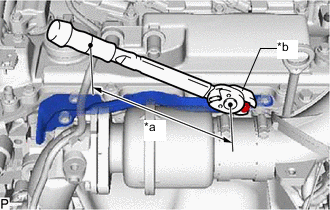
*a Torque Wrench Fulcrum Length *b 10 mm Union Nut Wrench Using a 10 mm union nut wrench, Tighten the bolt.
- Torque:
- Specified tightening torque
- 10 N*m { 102 kgf*cm, 7 ft.*lbf }
Tech Tips
-
Calculate the torque wrench reading when changing the fulcrum length of the torque wrench.
-
When using a 10 mm union nut wrench (fulcrum length of 22 mm (0.87 in.)) + torque wrench (fulcrum length of 155 mm (6.1 in.)): 9.0 N*m (92 kgf*cm, 80 in.*lbf)
-
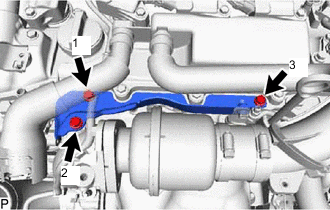
Tighten the 3 bolts in the order shown in the illustration.
- Torque:
- 10 N*m { 102 kgf*cm, 7 ft.*lbf }
-
-
INSTALL NO. 2 AIR CLEANER HOSE
-
Install the No. 2 air cleaner hose to the inlet compressor elbow and tighten the hose clamp.
- Torque:
- 6.3 N*m { 64 kgf*cm, 56 in.*lbf }
-
Connect the No. 4 ventilation hose to the No. 2 air cleaner hose and slide the clip to secure it.
-
-
INSTALL INTAKE AIR CONNECTOR
-
Temporarily install the intake air connector to the No. 2 air cleaner hose with the hose clamp.
-
Temporarily connect the intake air connector to the outlet compressor elbow and No. 1 air tube with the 2 bolts.
-
Tighten the 2 bolts.
- Torque:
- 21 N*m { 214 kgf*cm, 15 ft.*lbf }
-
Tighten the hose clamp.
- Torque:
- 6.3 N*m { 64 kgf*cm, 56 in.*lbf }
-
-
INSTALL AIR CLEANER CAP WITH AIR CLEANER HOSE
-
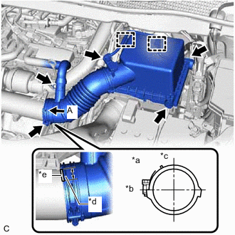
*a View A *b Front *c Upper *d Cutout *e Protrusion Install the air cleaner cap with air cleaner hose to the intake air connector and tighten the hose clamp.
-
Engage the 2 clamps to install the air cleaner cap with air cleaner hose to the air cleaner case sub-assembly.
-
Connect the ventilation hose to the air cleaner hose and slide the clip to secure it.
-
Engage the 2 wire harness clamps to the air cleaner cap sub-assembly.
-
Connect the intake mass air flow meter sub-assembly connector.
-
-
INSTALL FRONT EXHAUST PIPE ASSEMBLY
-
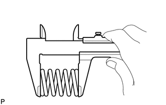
Using a vernier caliper, measure the free length of the compression springs.
Standard Length 43.0 mm (1.69 in.) Minimum Free Length 41.5 mm (1.63 in.) If the free length is less than the minimum, replace the compression spring.
-
Temporarily install a new exhaust pipe gasket to the exhaust manifold converter sub-assembly (TWC: Front Catalyst).
-
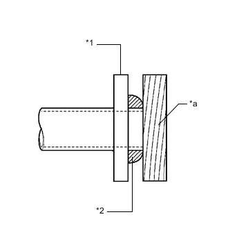
*1 Exhaust Manifold Converter Sub-assembly (TWC: Front Catalyst) *2 Exhaust Pipe Gasket *a Wooden Block Using a plastic hammer and wooden block, tap in the exhaust pipe gasket until its surface is flush with the exhaust manifold converter sub-assembly (TWC: Front Catalyst).
Note
-
Be sure to install the exhaust pipe gasket in the correct direction.
-
Do not reuse the exhaust pipe gasket.
-
Do not damage the exhaust pipe gasket.
-
Do not push in the exhaust pipe gasket by using the exhaust pipe when connecting it.
-
-
Connect the front exhaust pipe assembly to the exhaust manifold converter sub-assembly (TWC: Front Catalyst) with the 2 compression springs and 2 bolts.
- Torque:
- 48 N*m { 489 kgf*cm, 35 ft.*lbf }
Tech Tips
After installation, check that the space between the flanges of the exhaust manifold converter sub-assembly (TWC: Front Catalyst) and front exhaust pipe assembly is consistent front-to-rear and left-to-right.
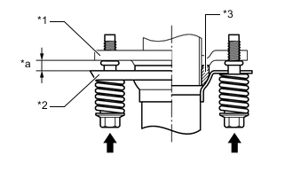
*1 Exhaust Manifold Converter Sub-assembly (TWC: Rear Catalyst) *2 Front Exhaust Pipe Assembly *3 Exhaust Pipe Gasket *a Space between Flanges: 9.5 mm (0.374 in.) -
Install a new exhaust pipe gasket to the front exhaust pipe assembly.
-
Install the front exhaust pipe assembly to the center exhaust pipe assembly (TWC: Rear Catalyst) with the 2 nuts.
- Torque:
- 55 N*m { 561 kgf*cm, 41 ft.*lbf }
-
-
INSPECT FOR EXHAUST GAS LEAK
-
INSTALL NO. 1 ENGINE COVER SUB-ASSEMBLY