FUEL PUMP(for High Pressure) INSTALLATION
CAUTION / NOTICE / HINT
Note
This procedure includes the installation of small-head bolts. Refer to Small-Head Bolts of Basic Repair Hint to identify the small-head bolts.
PROCEDURE
-
TEMPORARILY INSTALL FUEL PUMP ASSEMBLY (for Bank 2)
-
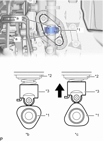
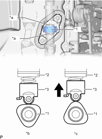
*1 No. 2 Camshaft *2 Fuel Pump Assembly *3 Fuel Pump Lifter Assembly *a Fuel Pump Lifter Housing *b Correct *c Incorrect Turn the crankshaft pulley until the flat of the camshaft faces the fuel pump lifter assembly.
Tech Tips
This prevents the camshaft nose from pushing up the fuel pump lifter assembly when installing the fuel pump assembly and No. 2 fuel pipe sub-assembly.
-
Apply 30 cc (1.83 cu.in.) of engine oil to the fuel pump lifter housing.
-
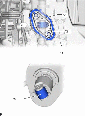
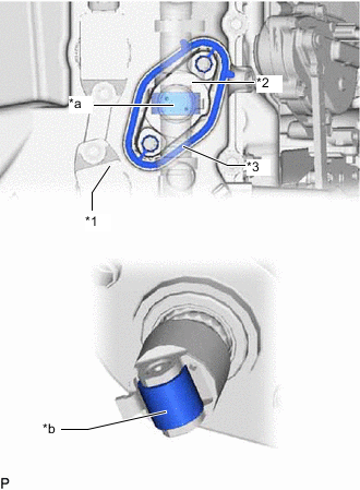
*1 Cylinder Head Cover Sub-assembly LH *2 Fuel Pump Lifter Housing *3 Gasket *a Pump Drive Cam (Engine Oil Application Area) *b Fuel Pump Lifter (Engine Oil Application Area) Apply engine oil to the pump drive cam and fuel pump lifter assembly.
-
Install a new gasket to the cylinder head cover sub-assembly LH.
-
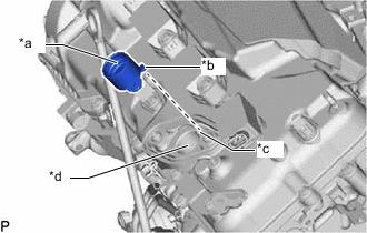
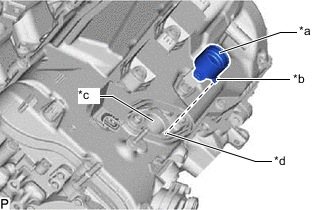
*a Fuel Pump Lifter Assembly (Engine Oil Application Area) *b Protrusion *c Groove *d Fuel Pump Lifter Housing (Engine Oil Application Area) Apply engine oil to the inside of the fuel pump lifter housing and the outside of the fuel pump lifter assembly.
-
Set the fuel pump lifter assembly on the fuel pump lifter housing as shown in the illustration.
Tech Tips
Align the protrusion of the fuel pump lifter assembly with the groove of the fuel pump lifter housing.
-
Apply engine oil to a new O-ring and install it to the fuel pump assembly.
Note
Do not damage the O-ring.
-
Set the fuel pump assembly on the cylinder head cover sub-assembly LH with the 2 bolts.
Tech Tips
Install the fuel pump assembly so that it can still be moved.
-
Connect the connector to the fuel pump assembly.
-
Install the wire harness clamp bracket to the cylinder head cover sub-assembly LH.
- Torque:
- 10 N*m { 102 kgf*cm, 7 ft.*lbf }
-
Attach the clamp and connect the No. 5 engine wire to the wire harness clamp bracket.
-
Connect the connector to the No. 5 engine wire.
-
-
TEMPORARILY INSTALL NO. 2 FUEL PIPE SUB-ASSEMBLY
-
Temporarily install the No. 2 fuel pipe sub-assembly to the fuel pump assembly and No. 2 fuel delivery pipe sub-assembly LH withe the 2 union nuts.
Note
If the 2 union nuts do not make contact, loosen the No. 2 fuel delivery pipe sub-assembly LH installation bolt and adjust so that the 2 union bolts make contact.
Tech Tips
Install the union nut by hand until all of the threads make contact.
-
-
TIGHTEN FUEL PUMP ASSEMBLY (for Bank 2)
-
Tighten the 2 bolts.
- Torque:
- 28 N*m { 286 kgf*cm, 21 ft.*lbf }
-
-
TIGHTEN NO. 2 FUEL PIPE SUB-ASSEMBLY
-
Install the No. 2 fuel pipe sub-assembly to the cylinder head cover sub-assembly LH with the bolts.
- Torque:
- 10 N*m { 102 kgf*cm, 7 ft.*lbf }
-
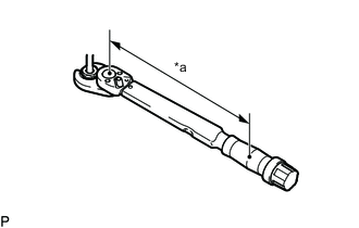
*a Torque Wrench Fulcrum Length Using a 17 mm union nut wrench, tighten the union nut on the fuel pump assembly side of the No. 2 fuel pipe sub-assembly.
- Torque:
- Specified tightening torque
- 35 N*m { 357 kgf*cm, 26 ft.*lbf }
Note
Do not adjust the torque in the loosening direction.
Tech Tips
-
Calculate the torque wrench reading when changing the fulcrum length of the torque wrench.
-
When using a 17 mm union nut wrench (fulcrum length of 30 mm (1.18 in.)) + torque wrench (fulcrum length of 180 mm (7.09 in.)): 30 N*m (306 kgf*cm, 22 ft.*lbf)
-
*a Torque Wrench Fulcrum Length Using a 17 mm union nut wrench, tighten the union nut on the No. 2 fuel delivery pipe sub-assembly LH side of the No. 2 fuel pipe sub-assembly.
- Torque:
- Specified tightening torque
- 35 N*m { 357 kgf*cm, 26 ft.*lbf }
Note
Do not adjust the torque in the loosening direction.
Tech Tips
-
Calculate the torque wrench reading when changing the fulcrum length of the torque wrench.
-
When using a 17 mm union nut wrench (fulcrum length of 30 mm (1.18 in.)) + torque wrench (fulcrum length of 180 mm (7.09 in.)): 30 N*m (306 kgf*cm, 22 ft.*lbf)
-
-
TEMPORARILY INSTALL FUEL PUMP ASSEMBLY (for Bank 1)
-
*1 Camshaft *2 Fuel Pump Assembly *3 Fuel Pump Lifter Assembly *a Fuel Pump Lifter Housing *b Correct *c Incorrect Turn the crankshaft pulley until the flat of the camshaft faces the fuel pump lifter assembly.
Tech Tips
This prevents the camshaft nose from pushing up the fuel pump lifter assembly when installing the fuel pump assembly and No. 1 fuel pipe sub-assembly.
-
Apply 30 cc (1.83 cu.in.) of engine oil to the fuel pump lifter housing.
-
*1 Cylinder Head Cover Sub-assembly LH *2 Fuel Pump Lifter Housing *3 Gasket *a Pump Drive Cam (Engine Oil Application Area) *b Fuel Pump Lifter (Engine Oil Application Area) Apply engine oil to the pump drive cam and fuel pump lifter assembly.
-
Install a new gasket to the cylinder head cover sub-assembly RH.
-
*a Fuel Pump Lifter Assembly (Engine Oil Application Area) *b Protrusion *c Fuel Pump Lifter Housing (Engine Oil Application Area) *d Groove Apply engine oil to the inside of the fuel pump lifter housing and the outside of the fuel pump lifter assembly.
-
Set the fuel pump lifter assembly on the fuel pump lifter housing as shown in the illustration.
Tech Tips
Align the protrusion of the fuel pump lifter assembly with the groove of the fuel pump lifter housing.
-
Apply engine oil to a new O-ring and install it to the fuel pump assembly.
Note
Do not damage the O-ring.
-
Set the fuel pump assembly on the cylinder head cover sub-assembly RH with the 2 bolts.
Tech Tips
Install the fuel pump assembly so that it can still be moved.
-
Connect the connector to the fuel pump assembly.
-
-
TEMPORARILY INSTALL NO. 1 FUEL PIPE SUB-ASSEMBLY
-
Temporarily install the No. 1 fuel pipe sub-assembly to the fuel pump assembly and No. 2 fuel delivery pipe sub-assembly RH withe the 2 union nuts.
Note
If the 2 union nuts do not make contact, loosen the No. 2 fuel delivery pipe sub-assembly RH installation bolt and adjust so that the 2 union bolts make contact.
Tech Tips
Install the union nut by hand until all of the threads make contact.
-
-
TIGHTEN FUEL PUMP ASSEMBLY (for Bank 1)
-
Tighten the 2 bolts.
- Torque:
- 28 N*m { 286 kgf*cm, 21 ft.*lbf }
-
-
TIGHTEN NO. 1 FUEL PIPE SUB-ASSEMBLY
-
Install the No. 1 fuel pipe sub-assembly to the cylinder head cover sub-assembly RH with the bolts.
- Torque:
- 10 N*m { 102 kgf*cm, 7 ft.*lbf }
-
*a Torque Wrench Fulcrum Length Using a 17 mm union nut wrench, tighten the union nut on the fuel pump assembly side of the No. 1 fuel pipe sub-assembly.
- Torque:
- Specified tightening torque
- 35 N*m { 357 kgf*cm, 26 ft.*lbf }
Note
Do not adjust the torque in the loosening direction.
Tech Tips
-
Calculate the torque wrench reading when changing the fulcrum length of the torque wrench.
-
When using a 17 mm union nut wrench (fulcrum length of 30 mm (1.18 in.)) + torque wrench (fulcrum length of 180 mm (7.09 in.)): 30 N*m (306 kgf*cm, 22 ft.*lbf)
-
*a Torque Wrench Fulcrum Length Using a 17 mm union nut wrench, tighten the union nut on the No. 2 fuel delivery pipe sub-assembly RH side of the No. 1 fuel pipe sub-assembly.
- Torque:
- Specified tightening torque
- 35 N*m { 357 kgf*cm, 26 ft.*lbf }
Note
Do not adjust the torque in the loosening direction.
Tech Tips
-
Calculate the torque wrench reading when changing the fulcrum length of the torque wrench.
-
When using a 17 mm union nut wrench (fulcrum length of 30 mm (1.18 in.)) + torque wrench (fulcrum length of 180 mm (7.09 in.)): 30 N*m (306 kgf*cm, 22 ft.*lbf)
-
-
INSTALL NO. 1 VACUUM SWITCHING VALVE ASSEMBLY
-
INSTALL NO. 1 FUEL DELIVERY PIPE SUB-ASSEMBLY RH AND NO. 1 FUEL DELIVERY PIPE SUB-ASSEMBLY LH
-
CONNECT CABLE TO NEGATIVE BATTERY TERMINAL
Note
When disconnecting the cable, some systems need to be initialized after the cable is reconnected.
-
INSPECT FOR FUEL LEAK
-
PERFORM INITIALIZATION
-
Perform "Inspection After Repair" after replacing the fuel pressure sensor.
-
w/ Canistaer Pump Module:
-
w/o Canistaer Pump Module:
-
-