REAR POWER SEAT CONTROL SYSTEM, Diagnostic DTC:B2651
| DTC Code | DTC Name |
|---|---|
| B2651 | Reclining Sensor Malfunction |
DESCRIPTION
When the position control ECU assembly does not receive a sensor signal despite forward or rearward movement of the seat by power seat motor operation, this DTC is stored.
| DTC No. | Detection Item | DTC Detection Condition | Trouble Area |
|---|---|---|---|
| B2651 | Reclining Sensor Malfunction | The forward and rearward lock detection position of the sensor is the same. |
|
WIRING DIAGRAM
-
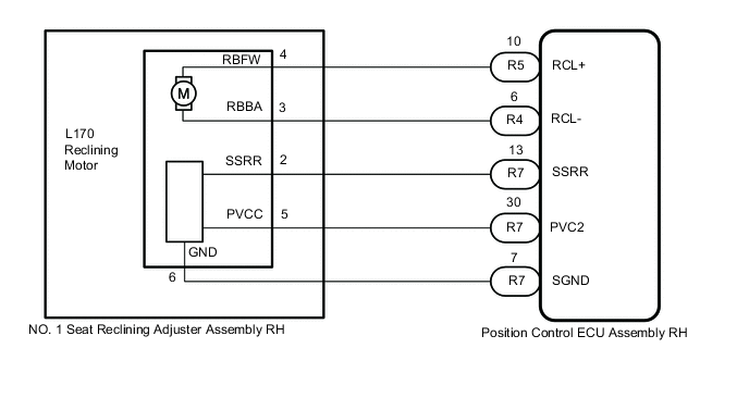
for Rear Seat RH:
-
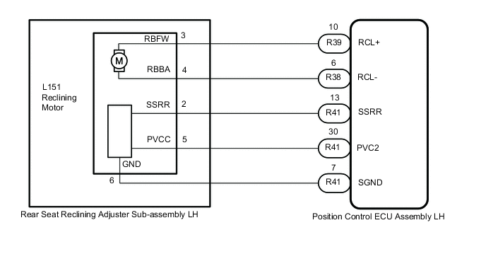
for Rear Seat LH:
CAUTION / NOTICE / HINT
Note
Initializing the position control ECU assembly will clear the seat position memory.
Tech Tips
-
Make sure to initialize the position control ECU assembly after replacing the seat assembly or any related parts (including removal and installation).
-
Before initializing the seat ECU, make sure that the D/C CUT fuse is normal.
-
When any of the following conditions are met, the seat position Information in the position control ECU assembly will be cleared.
-
The engine switch is turned off with any of the seat switches being operated and the D/C CUT fuse removed.
-
The engine switch is turned off within 1 second of any of the seat switches being operated with the D/C CUT fuse removed.
PROCEDURE
-
CLEAR DTC
-
Clear the DTCs.
Body Electrical > Rear Right Seat > Clear DTCs
Body Electrical > Rear Left Seat > Clear DTCsResult Proceed to NEXT
NEXT 
-
-
CHECK FOR DTC
-
Check for DTCs.
Body Electrical > Rear Right Seat > Trouble Codes
Body Electrical > Rear Left Seat > Trouble CodesOK DTC B2651 is not output. Result Result Proceed to DTC B2651 is not output A DTC B2651 output from "Rear Right Seat" B DTC B2651 output from "Rear Left Seat" C
A 
USE SIMULATION METHOD TO CHECK Click here
C 
PERFORM ACTIVE TEST USING GTS (SEAT RECLINING) Click here
B
-
-
PERFORM ACTIVE TEST USING GTS (SEAT RECLINING)
-
Connect the GTS to the DLC3.
-
Turn the engine switch on (IG).
-
Turn the GTS on.
-
Enter the following menus: Body Electrical / Rear Right Seat / Active Test.
-
Perform the Active Test according to the display on the GTS.
Body Electrical > Rear Right Seat > Active TestTester Display Measurement Item Control Range Diagnostic Note Seat Reclining Seat reclining operation OFF/Rear/Front -
Body Electrical > Rear Right Seat > Active TestTester Display Seat Reclining OK Motor operates normally. Result Proceed to OK NG
NG
INSPECT REAR SEAT RECLINING ADJUSTER SUB-ASSEMBLY RH (RECLINING MOTOR) Click here
OK
-
-
CHECK POSITION CONTROL ECU ASSEMBLY RH (RECLINING MOTOR CIRCUIT)
-
Disconnect the rear reclining adjuster sub-assembly RH (reclining motor) connector.
-
Measure the voltage according to the value(s) in the table below.
Standard Voltage Tester Connection Switch Condition Specified Condition L170-3 (RBBA) - L170-6 (GND) Reclining switch on 4.8 to 5.1 V L170-5 (PVCC) - L170-6 (GND) Reclining switch on 4.8 to 5.1 V Result Proceed to OK NG
OK
REPLACE REAR SEAT RECLINING ADJUSTER SUB-ASSEMBLY RH Click here
NG
-
-
CHECK HARNESS AND CONNECTOR (POSITION CONTROL ECU ASSEMBLY RH - REAR SEAT RECLINING ADJUSTER SUB-ASSEMBLY RH (RECLINING MOTOR))
-
Disconnect the R7 position control ECU assembly RH connector.
-
Disconnect the L170 rear seat reclining adjuster sub-assembly RH (reclining motor) connector.
-
Measure the resistance according to the value(s) in the table below.
Standard Resistance Tester Connection Condition Specified Condition R7-13 (SSRR) - L170-2 (SSRR) Always Below 1 Ω R7-13 (SSRR) or L170-2 (SSRR) - Other terminals and body ground Always 10 kΩ or higher R7-30 (PVC2) - L170-5 (PVCC) Always Below 1 Ω R7-30 (PVC2) or L170-5 (PVCC) - Other terminals and body ground Always 10 kΩ or higher R7-7 (SGND) - L170-6 (GND) Always Below 1 Ω Result Proceed to OK NG
OK
REPLACE POSITION CONTROL ECU ASSEMBLY RH Click here
NG
REPAIR OR REPLACE HARNESS OR CONNECTOR
-
-
INSPECT REAR SEAT RECLINING ADJUSTER SUB-ASSEMBLY RH (RECLINING MOTOR)
-
Remove the rear seat reclining adjuster sub-assembly RH (reclining motor).
-
Inspect the rear seat reclining adjuster sub-assembly RH (reclining motor).
Result Proceed to OK NG
NG
REPLACE REAR SEAT RECLINING ADJUSTER SUB-ASSEMBLY RH Click here
OK
-
-
CHECK HARNESS AND CONNECTOR (POSITION CONTROL ECU ASSEMBLY RH - REAR SEAT RECLINIG ADJUSTER SUB-ASSEMBLY RH (RECLINING MOTOR))
-
Disconnect the R4 and R5 position control ECU assembly RH connectors.
-
Disconnect the L170 rear seat reclining adjuster sub-assembly RH (reclining motor) connector.
-
Measure the resistance according to the value(s) in the table below.
Standard Resistance Tester Connection Condition Specified Condition R5-10 (RCL+) - L170-4 (PBFW) Always Below 1 Ω R5-10 (RCL+) or L170-4 (PBFW) - Other terminals and body ground Always 10 kΩ or higher R4-6 (RCL-) - L170-3 (RBBA) Always Below 1 Ω R4-6 (RCL-) or L170-3 (RBBA) - Other terminals and body ground Always 10 kΩ or higher Result Proceed to OK NG
OK
REPLACE POSITION CONTROL ECU ASSEMBLY RH Click here
NG
REPAIR OR REPLACE HARNESS OR CONNECTOR
-
-
PERFORM ACTIVE TEST USING GTS (SEAT RECLINING)
-
Connect the GTS to the DLC3.
-
Turn the engine switch on (IG).
-
Turn the GTS on.
-
Enter the following menus: Body Electrical / Rear Left Seat / Active Test.
-
Perform the Active Test according to the display on the GTS.
Body Electrical > Rear Left Seat > Active TestTester Display Measurement Item Control Range Diagnostic Note Seat Reclining Seat reclining operation OFF/Rear/Front -
Body Electrical > Rear Left Seat > Active TestTester Display Seat Reclining OK Motor operates normally. Result Proceed to OK NG
NG
INSPECT REAR SEAT RECLINING ADJUSTER SUB-ASSEMBLY LH (RECLINING MOTOR) Click here
OK
-
-
CHECK POSITION CONTROL ECU ASSEMBLY LH (RECLINING MOTOR CIRCUIT)
-
Disconnect the rear seat reclining adjuster sub-assembly LH (reclining motor) connector.
-
Measure the voltage according to the value(s) in the table below.
Standard Voltage Tester Connection Switch Condition Specified Condition L151-4 (RBBA) - L151-6 (GND) Reclining switch on 4.8 to 5.1 V L151-5 (PVCC) - L151-6 (GND) Reclining switch on 4.8 to 5.1 V Result Proceed to OK NG
OK
REPLACE REAR SEAT RECLINING ADJUSTER SUB-ASSEMBLY LH Click here
NG
-
-
CHECK HARNESS AND CONNECTOR (POSITION CONTROL ECU ASSEMBLY LH - REAR SEAT RECLINING ADJUSTER SUB-ASSEMBLY LH (RECLINING MOTOR))
-
Disconnect the R41 position control ECU assembly LH connector.
-
Disconnect the L151 rear seat reclining adjuster sub-assembly LH (reclining) connector.
-
Measure the resistance according to the value(s) in the table below.
Standard Resistance Tester Connection Condition Specified Condition R41-13 (SSRR) - L151-2 (SSRR) Always Below 1 Ω R41-13 (SSRR) or L151-2 (SSRR) - Other terminals and body ground Always 10 kΩ or higher R41-30 (PVC2) - L151-5 (PVCC) Always Below 1 Ω R41-30 (PVC2) or L151-5 (PVCC) - Other terminals and body ground Always 10 kΩ or higher R41-7 (SGND) - L151-6 (GND) Always Below 1 Ω Result Proceed to OK NG
OK
REPLACE POSITION CONTROL ECU ASSEMBLY LH Click here
NG
REPAIR OR REPLACE HARNESS OR CONNECTOR
-
-
INSPECT REAR SEAT RECLINING ADJUSTER SUB-ASSEMBLY LH (RECLINING MOTOR)
-
Remove the rear seat reclining adjuster sub-assembly LH (reclining motor).
-
Inspect the rear seat reclining adjuster sub-assembly LH (reclining motor).
Result Proceed to OK NG
NG
REPLACE REAR SEAT RECLINING ADJUSTER SUB-ASSEMBLY LH Click here
OK
-
-
CHECK HARNESS AND CONNECTOR (POSITION CONTROL ECU ASSEMBLY LH - REAR SEAT RECLINIG ADJUSTER SUB-ASSEMBLY LH (RECLINING MOTOR))
-
Disconnect the R38 and R39 position control ECU assembly LH connectors.
-
Disconnect the L151 rear seat reclining adjuster sub-assembly LH (reclining motor) connector.
-
Measure the resistance according to the value(s) in the table below.
Standard Resistance Tester Connection Condition Specified Condition R39-10 (RCL+) - L151-3 (PBFW) Always Below 1 Ω R39-10 (RCL+) or L151-3 (PBFW) - Other terminals and body ground Always 10 kΩ or higher R38-6 (RCL-) - L151-4 (RBBA) Always Below 1 Ω R38-6 (RCL-) or L151-4 (RBBA) - Other terminals and body ground Always 10 kΩ or higher Result Proceed to OK NG
OK
REPLACE POSITION CONTROL ECU ASSEMBLY LH Click here
NG
REPAIR OR REPLACE HARNESS OR CONNECTOR
-