VEHICLE STABILITY CONTROL SYSTEM VSC OFF Indicator Light Remains ON
DESCRIPTION
Pressing the VSC OFF switch turns off traction control and pressing and holding this switch turns off traction control and VSC. If VSC turns off, the VSC OFF indicator light will come on.
for 4WD:
When the transfer position is L4, VSC is prohibited and the VSC OFF indicator light turns on.
w/ Rear Differential Lock:
When the rear differential is locked, VSC is prohibited, and the VSC OFF and TRC OFF indicator lights turn on.
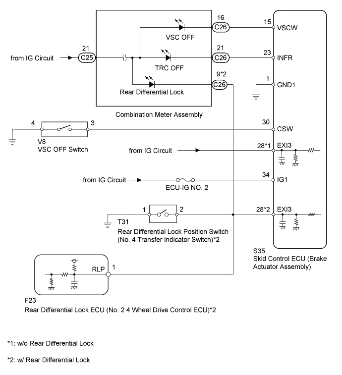
WIRING DIAGRAM
INSPECTION PROCEDURE
Note
-
for 4WD:
As there may be malfunctions in the transfer system related to when the transfer operates in L4, check the transfer system first Click here.
-
After replacing the brake actuator assembly, perform calibration Click here.
-
Before disconnecting the connector, make sure that there are no problems with the connection.
-
After disconnecting the connector, make sure that the connector case and terminals are not deformed or corroded.
PROCEDURE
-
READ VALUE USING INTELLIGENT TESTER (TRC/VSC OFF MODE)
-
Turn the ignition switch off.
-
Connect the intelligent tester to the DLC3.
-
Turn the ignition switch to ON.
-
Turn the intelligent tester on.
-
Enter the following menus: Chassis / ABS/VSC/TRC / Data List.
ABS/VSC/TRC Tester Display Measurement Item / Range Normal Condition Diagnostic Note TRC/VSC Off Mode VSC OFF switch / Normal, Unknown, TRC OFF or VSC OFF Normal: Normal mode
TRC OFF: TRC off mode
VSC OFF: VSC off mode
- -
Check that the mode display changes according to VSC OFF switch operation.
OK The intelligent tester display changes according to VSC OFF switch operation.
NG 
INSPECT VSC OFF SWITCH Click here
OK 
-
-
INSPECT BRAKE ACTUATOR ASSEMBLY
-
Turn the ignition switch off.
-
Disconnect the skid control ECU (brake actuator assembly) connector.
-
Turn the ignition switch to ON.
-
Check the state of the VSC OFF indicator light.
Result Result Proceed to VSC OFF indicator light turns off for LHD A for RHD B VSC OFF indicator light does not turn off C
B 
REPLACE BRAKE ACTUATOR ASSEMBLY Click here
C
CHECK HARNESS AND CONNECTOR (SKID CONTROL ECU - COMBINATION METER) Click here
A 
REPLACE BRAKE ACTUATOR ASSEMBLY Click here
-
-
INSPECT VSC OFF SWITCH
-
Turn the ignition switch off.
-
Remove the VSC OFF switch Click here.
-
Inspect the VSC OFF switch Click here.
NG
REPLACE VSC OFF SWITCH Click here
OK
-
-
CHECK HARNESS AND CONNECTOR (SKID CONTROL ECU - VSC OFF SWITCH)
-
Turn the ignition switch off.
-
Disconnect the VSC OFF switch connector.
-
Disconnect the skid control ECU (brake actuator assembly) connector.
-
Measure the resistance according to the value(s) in the table below.
Standard Resistance Tester Connection Condition Specified Condition S35-30 (CSW) - V8-3 Always Below 1 Ω S35-30 (CSW) - Body ground Always 10 kΩ or higher V8-4 - Body ground Always Below 1 Ω
NG
REPAIR OR REPLACE HARNESS OR CONNECTOR
OK
-
-
CHECK TERMINAL VOLTAGE (EXI3 TERMINAL)
-
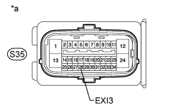
Text in Illustration *a Front view of wire harness connector
(to Skid Control ECU [Brake Actuator Assembly])
Turn the ignition switch off.
-
Disconnect the skid control ECU (brake actuator assembly) connector.
-
Measure the voltage according to the value(s) in the table below.
Standard Voltage Tester Connection Switch Condition Specified Condition S35-28 (EXI3) - Body ground Ignition switch ON 11 to 14 V Result Result Proceed to NG w/ Rear Differential Lock A w/o Rear Differential Lock B OK for LHD C for RHD D
B
REPAIR OR REPLACE HARNESS OR CONNECTOR
C
REPLACE BRAKE ACTUATOR ASSEMBLY Click here
D
REPLACE BRAKE ACTUATOR ASSEMBLY Click here
A
-
-
CHECK HARNESS AND CONNECTOR (EXI3 TERMINAL CIRCUIT)
-
Turn the ignition switch off.
-
Disconnect the rear differential lock position switch (No. 4 transfer indicator switch) connector.
-
Disconnect the rear differential lock ECU (No. 2 4 wheel drive control ECU) connector.
-
Disconnect the skid control ECU (brake actuator assembly) connector.
-
Disconnect the C26 combination meter connector.
-
Measure the resistance according to the value(s) in the table below.
Standard Resistance Tester Connection Condition Specified Condition S35-28 (EXI3) - T31-2 Always Below 1 Ω S35-28 (EXI3) - C26-9 Always Below 1 Ω S35-28 (EXI3) - F23-1 (RLP) Always Below 1 Ω S35-28 (EXI3) - Body ground Always 10 kΩ or higher
NG
REPAIR OR REPLACE HARNESS OR CONNECTOR
OK
-
-
INSPECT DIFFERENTIAL LOCK SYSTEM
-
Inspect rear differential lock system Click here.
NG
GO TO DIFFERENTIAL LOCK SYSTEM (PROBLEM SYMPTOMS TABLE) Click here
OK
-
-
CHECK HARNESS AND CONNECTOR (SKID CONTROL ECU - COMBINATION METER)
-
Turn the ignition switch off.
-
Disconnect the skid control ECU (brake actuator assembly) connector.
-
Disconnect the C26 combination meter connector.
-
Measure the resistance according to the value(s) in the table below.
Standard Resistance Tester Connection Condition Specified Condition S35-15 (VSCW) - C26-16 Always Below 1 Ω S35-15 (VSCW) - Body ground Always 10 kΩ or higher
NG
REPAIR OR REPLACE HARNESS OR CONNECTOR
OK
GO TO METER / GAUGE SYSTEM (HOW TO PROCEED WITH TROUBLESHOOTING) Click here
-