CYLINDER HEAD DISASSEMBLY

CAUTION / NOTICE / HINT
The necessary procedures (adjustment, calibration, initialization, or registration) that must be performed after parts are removed, installed, or replaced during the cylinder head removal/installation are shown below.
| Replaced Part or Performed Procedure | Necessary Procedure | Effect/Inoperative Function when Necessary Procedure not Performed | Link |
|---|---|---|---|
| Battery terminal is disconnected/reconnected | Drive the vehicle until stop and start control is permitted (approximately 5 to 60 minutes) | Stop and start system | |
| Memorize steering angle neutral point | LKA/LDA system | ||
| Parking support brake system*1 | |||
| Pre-collision system | |||
| Adaptive high beam system | |||
Lighting system (EXT) |
|||
| Variable gear ratio steering system | |||
| Parking assist monitor system | |||
| Panoramic view monitor system | |||
| Initialize rear door sunshade system | Rear door sunshade system | ||
| Initialize power trunk lid system | Power trunk lid system | ||
|
Inspection after repairs |
|
w/ Canister Pump Module: w/o Canister Pump Module: |
| Replacement of engine assembly | Inspection after repair |
|
|
|
|
for AGA0E: for AGA0F: |
|
| ECM | Vehicle Identification Number (VIN) registration | DTC P063051 is output | w/ Canister Pump Module: w/o Canister Pump Module: |
Heavy Knock History |
- | ||
for AGA0E: |
|
|
for Initialization: for Registration: |
for AGA0E: |
ATF thermal degradation estimate reset | The value of the Data List item "ATF Thermal Degradation Estimate" is not estimated correctly. | |
for AGA0F: |
|
|
for Initialization: for Registration: |
for AGA0F: |
ATF thermal degradation estimate reset | The value of the Data List item "ATF Thermal Degradation Estimate" is not estimated correctly. | |
| Parts between the steering wheel and tires have been removed/installed, replaced or adjusted | Perform Actuator Angle Neutral Point Calibration and Initialization |
|
|
| Front bumper assembly (Including removal and installation) |
|
Parking support brake system | |
| Front television camera view adjustment | Panoramic view monitor system | ||
| Suspension, tires, etc |
|
Parking support brake system | |
|
Panoramic view monitor system | ||
| Rear television camera assembly optical axis (Back camera position setting) | Parking assist monitor system |
Click here Click here
*2: Set the transmission compensation code for the new automatic transmission.
Tech Tips
-
Use the same procedure for the Bank 2 side and Bank 1 side.
-
The following procedure is for the Bank 1 side.
PROCEDURE
-
REMOVE CYLINDER HEAD INTAKE VALVE LH
-
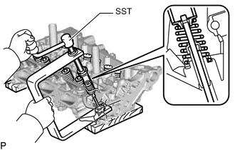
Using SST, compress each compression spring and remove the 6 cylinder head valve spring retainer locks.
- SST
- 09202-70020 ( 09202-01010, 09202-01020 )
- 09202-00021
-
Remove the 6 cylinder head valve spring retainers, 6 cylinder head intake valve compression springs and 6 cylinder head intake valves from the cylinder head sub-assembly LH.
Tech Tips
Arrange the removed parts in the correct order.
-
-
REMOVE CYLINDER HEAD EXHAUST VALVE LH
CAUTION:
-
The exhaust valve is filled with sodium. Sodium is a strong alkali which may produce a dangerous chemical reaction. Therefore, be very careful when handling and disposing of it.
-
Do not disassemble the exhaust valve for the following reasons: 1) If sodium enters your eyes, vision loss may occur. 2) If sodium contacts your skin, burns may occur. 3) If sodium is exposed to a flame and starts a fire due to the chemical reaction that takes place, burns may occur.
-
If the exhaust valve is damaged, remove the valve and perform the proper procedures to dispose of the sodium. (disposal preparation and actual disposal)
-
When removing a damaged exhaust valve, always wear rubber gloves and safety glasses.
-
Do not cut the exhaust valve to take out the sodium.
Tech Tips
-
The sodium inside the exhaust valve is safe as long as the sodium is not exposed to air.
-
Exhaust valves filled with sodium can be identified by confirming the "NA" identification mark.
-
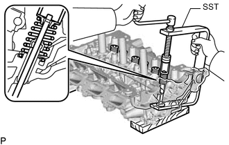
Using SST, compress each compression spring and remove the 6 cylinder head valve spring retainer locks.
- SST
- 09202-70020 ( 09202-01010, 09202-01020 )
- 09202-00021
-
Remove the 6 cylinder head valve spring retainers, 6 cylinder head exhaust valve compression springs and 6 cylinder head intake valves from the cylinder head sub-assembly LH.
Tech Tips
Arrange the removed parts in the correct order.
-
-
REMOVE CYLINDER HEAD INTAKE VALVE STEM OIL SEAL LH
-
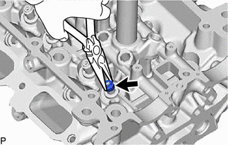
Using needle-nose pliers, remove the 6 cylinder head intake valve stem oil seals.
-
-
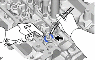
REMOVE CYLINDER HEAD EXHAUST VALVE STEM OIL SEAL LH
-
Using needle-nose pliers, remove the 6 cylinder head exhaust valve stem oil seals.
-
-
REMOVE CYLINDER HEAD VALVE SPRING SEAT LH
-
Using compressed air and a magnet hand, remove the 12 cylinder head valve spring seats by blowing air onto them.
-
-
REMOVE NO. 1 STRAIGHT SCREW PLUG
Note
If water leaks from a No. 1 straight screw plug or the plug is corroded, replace it.
-
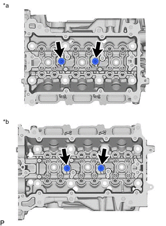
*a for Bank 1 *b for Bank 2 Using a 6 mm hexagon wrench, remove the 4 No. 1 straight screw plugs.
-
-
REMOVE NO. 2 STRAIGHT SCREW PLUG
Note
If water leaks from a No. 2 straight screw plug or the plug is corroded, replace it.
-
Using a 14 mm hexagon wrench, remove the 4 No. 2 straight screw plugs and 4 gaskets.
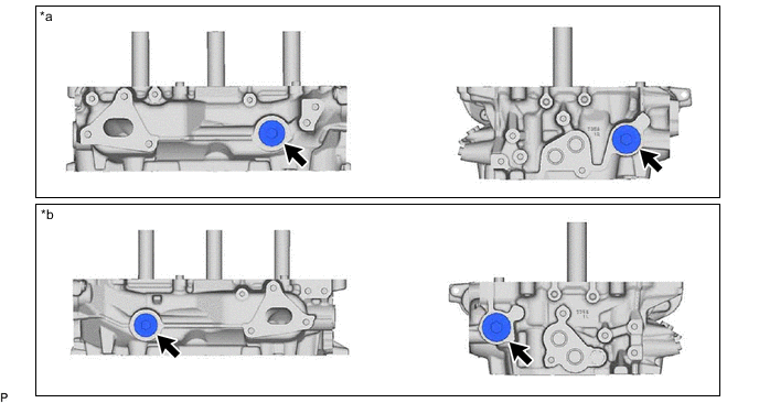
*a for Bank 1 *b for Bank 2
-
-
REMOVE STUD BOLT
Note
If the stud bolt is deformed or the threads are damaged, replace it.
-
REMOVE RING PIN
Note
It is not necessary to remove the ring pins unless they are being replaced.
-
DISPOSE OF EXHAUST VALVE
CAUTION:
-
The exhaust valve is filled with sodium. Sodium is a strong alkali which may produce a dangerous chemical reaction. Therefore, be very careful when handling and disposing of it.
-
Do not disassemble the exhaust valve for the following reasons: 1) If sodium enters your eyes, vision loss may occur. 2) If sodium contacts your skin, burns may occur. 3) If sodium is exposed to a flame and starts a fire due to the chemical reaction that takes place, burns may occur.
-
If the exhaust valve is damaged, remove the valve and perform the proper procedures to dispose of the sodium. (disposal preparation and actual disposal)
-
When removing a damaged exhaust valve, always wear rubber gloves and safety glasses.
-
Do not cut the exhaust valve to take out the sodium.
Note
If it is clearly stated that the industrial waste disposal method is dissolution, carry out the process below.
Tech Tips
-
The sodium inside the exhaust valve is safe as long as the sodium is not exposed to air.
-
Exhaust valves filled with sodium can be identified by confirming the "NA" identification mark.
-
Waste disposal preparation
CAUTION:
Always carry out the following when performing the disposal procedure.
-
Have a fire extinguisher close by.
-
Wear safety glasses.
-
Wear rubber gloves.
-
-
Waste disposal
-
Put on rubber gloves and remove the damaged exhaust valve from the cylinder head sub-assembly.
-
Add 10 L of water or more to a large receptacle (a bucket, oil can, etc.) in a well ventilated area.
-
Hold the damaged exhaust valve upright with pliers or large pair of tweezers and submerge it into the water.
CAUTION:
-
Fully submerge the damaged exhaust valve in water.
-
Do not allow any sparks or other flames near the receptacle as hydrogen gas is generated by the chemical reaction.
-
Stay 2 or 3 m or more away from the receptacle as a strong chemical reaction occurs.
-
-
-