STEERING GEAR(for 2WD) INSTALLATION

CAUTION / NOTICE / HINT
Tech Tips
-
Use the same procedure for RHD and LHD vehicles.
-
The procedure listed below is for LHD vehicles.
PROCEDURE
-
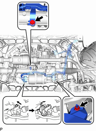
INSTALL RACK AND PINION POWER STEERING GEAR ASSEMBLY
-
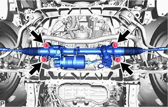
Install the rack and pinion power steering gear assembly with the 4 bolts and 4 nuts.
- Torque:
- 55 N*m { 561 kgf*cm, 41 ft.*lbf }
-
*a Torque Wrench Fulcrum Length for LHD, 8GR-FKS:
-
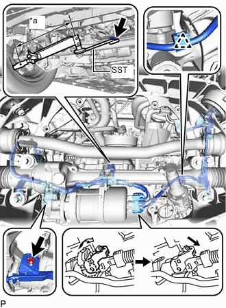
Using a SST and union nut wrench, Connect the wire harness clamp to the rack and pinion power steering gear assembly with the bolt.
- SST
- 09961-00950
- Torque:
- Specified tightening torque
- 9.0 N*m { 92 kgf*cm, 80 in.*lbf }
Tech Tips
-
Calculate the torque wrench reading when changing the fulcrum length of the torque wrench.
-
When using a union nut wrench (fulcrum length of 22 mm (0.866 in.)) + SST (fulcrum length of 150 mm (5.906 in.)) + torque wrench (fulcrum length of 300 mm (11.811 in.)): 5.7 N*m (58 kgf*cm, 50 in.*lbf)
-
Connect the wire harness clamp to the rack and pinion power steering gear assembly with the nut.
- Torque:
- 10 N*m { 102 kgf*cm, 7 ft.*lbf }
-
Connect the wire harness connector to the rack and pinion power steering gear assembly.
Tech Tips
When connecting the connector with lock lever, return the lock lever to its original position and securely push in the lock of the lock lever as shown in the illustration.
-
-
for RHD, 8GR-FKS:
-
*a Torque Wrench Fulcrum Length Using a SST and union nut wrench, Connect the wire harness clamp to the rack and pinion power steering gear assembly with the bolt.
- SST
- 09961-00950
- Torque:
- Specified tightening torque
- 9.0 N*m { 92 kgf*cm, 80 in.*lbf }
Tech Tips
-
Calculate the torque wrench reading when changing the fulcrum length of the torque wrench.
-
When using a union nut wrench (fulcrum length of 22 mm (0.866 in.)) + SST (fulcrum length of 150 mm (5.906 in.)) + torque wrench (fulcrum length of 300 mm (11.811 in.)): 5.7 N*m (58 kgf*cm, 50 in.*lbf)
-
Connect the wire harness clamp to the rack and pinion power steering gear assembly with the nut.
- Torque:
- 10 N*m { 102 kgf*cm, 7 ft.*lbf }
-
Connect the wire harness connector to the rack and pinion power steering gear assembly.
Tech Tips
When connecting the connector with lock lever, return the lock lever to its original position and securely push in the lock of the lock lever as shown in the illustration.
-
-
for LHD, V35A-FTS:
-
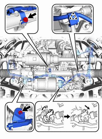
Connect the wire harness clamp to the rack and pinion power steering gear assembly with the bolt and nut.
- Torque:
- bolt
- 9.0 N*m { 92 kgf*cm, 80 in.*lbf }
- nut
- 10 N*m { 102 kgf*cm, 7 ft.*lbf }
-
Connect the wire harness connector to the rack and pinion power steering gear assembly.
Tech Tips
When connecting the connector with lock lever, return the lock lever to its original position and securely push in the lock of the lock lever as shown in the illustration.
-
-
for RHD, V35A-FTS:
-
Connect the wire harness clamp to the rack and pinion power steering gear assembly with the bolt and nut.
- Torque:
- bolt
- 9.0 N*m { 92 kgf*cm, 80 in.*lbf }
- nut
- 10 N*m { 102 kgf*cm, 7 ft.*lbf }
-
Connect the wire harness connector to the rack and pinion power steering gear assembly.
Tech Tips
When connecting the connector with lock lever, return the lock lever to its original position and securely push in the lock of the lock lever as shown in the illustration.
-
-
-
CONNECT TIE ROD ASSEMBLY LH
-
Connect the tie rod assembly LH to the front lower ball joint assembly with the nut.
- Torque:
- 60 N*m { 612 kgf*cm, 44 ft.*lbf }
-
Install a new clip.
Note
Further tighten the nut up to 60° if the holes for the clip are not aligned.
-
-
CONNECT TIE ROD ASSEMBLY RH
Tech Tips
Perform the same procedure as for the LH side.
-
CONNECT STEERING SLIDING WITH SHAFT YOKE SUB-ASSEMBLY (for 8GR-FKS)
-
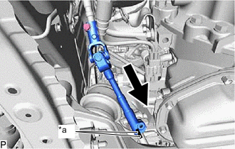
*a Matchmark Align the matchmarks on the steering sliding with shaft yoke sub-assembly with the matchmarks on the power steering link assembly.
-
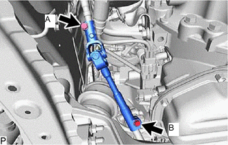
Install the bolt (B) and tighten the bolt (A).
- Torque:
- 35.3 N*m { 360 kgf*cm, 26 ft.*lbf }
-
-
CONNECT STEERING SLIDING WITH SHAFT YOKE SUB-ASSEMBLY (for V35A-FTS)
-
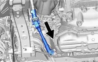
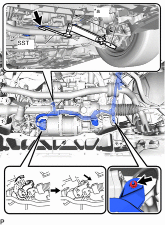
*a Matchmark Install the steering sliding with shaft yoke sub-assembly to the rack and pinion power steering gear assembly.
Note
Align the matchmarks on the steering sliding with shaft yoke sub-assembly and rack and pinion power steering gear assembly.
-
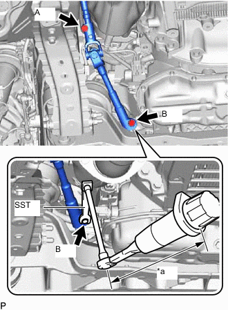
*a Torque Wrench Fulcrum Length Using a SST and 12 mm union nut wrench, install the bolt (B).
- SST
- 09961-00950
- Torque:
- Specified tightening torque
- 35.3 N*m { 360 kgf*cm, 26 ft.*lbf }
Tech Tips
-
Calculate the torque wrench reading when changing the fulcrum length of the torque wrench.
-
When using a union nut wrench (fulcrum length of 20 mm (0.787 in.)) + SST (fulcrum length of 150 mm (5.906 in.)) + torque wrench (fulcrum length of 180 mm (7.087 in.)): 18.2 N*m (186 kgf*cm, 13 ft.*lbf)
-
Tighten the bolt (A).
-
-
INSTALL STRUT BAR BRACKET SUPPORT SUB-ASSEMBLY
-
INSTALL FRONT SUSPENSION MEMBER BRACE
-
INSTALL NO. 2 ENGINE UNDER COVER ASSEMBLY
-
INSTALL TRANSMISSION UNDER COVER
-
INSTALL NO. 1 ENGINE UNDER COVER ASSEMBLY
-
INSTALL FRONT WHEELS
-
ALIGN FRONT WHEELS FACING STRAIGHT AHEAD
-
CONNECT CABLE TO NEGATIVE BATTERY TERMINAL
Note
-
When disconnecting the cable, some systems need to be initialized after the cable is reconnected.
-
-
INSTALL LUGGAGE COMPARTMENT MAT SUB-ASSEMBLY
-
INSPECT AND ADJUST FRONT WHEEL ALIGNMENT
-
ROTATION ANGLE SENSOR INITIALIZATION AND TORQUE SENSOR ZERO POINT CALIBRATION
-
PERFORM VARIABLE GEAR RATIO STEERING SYSTEM CALIBRATION (w/ VGRS)