AUDIO AND VISUAL SYSTEM, Diagnostic DTC:B1323, B1324, B1325, B1326
| DTC Code | DTC Name |
|---|---|
| B1323 | Lost Communication with Haptic Device |
| B1324 | Lost Communication with Meter |
| B1325 | Lost Communication with HUD |
| B1326 | Lost Communication with Clock Device (Local-CAN) |
DESCRIPTION
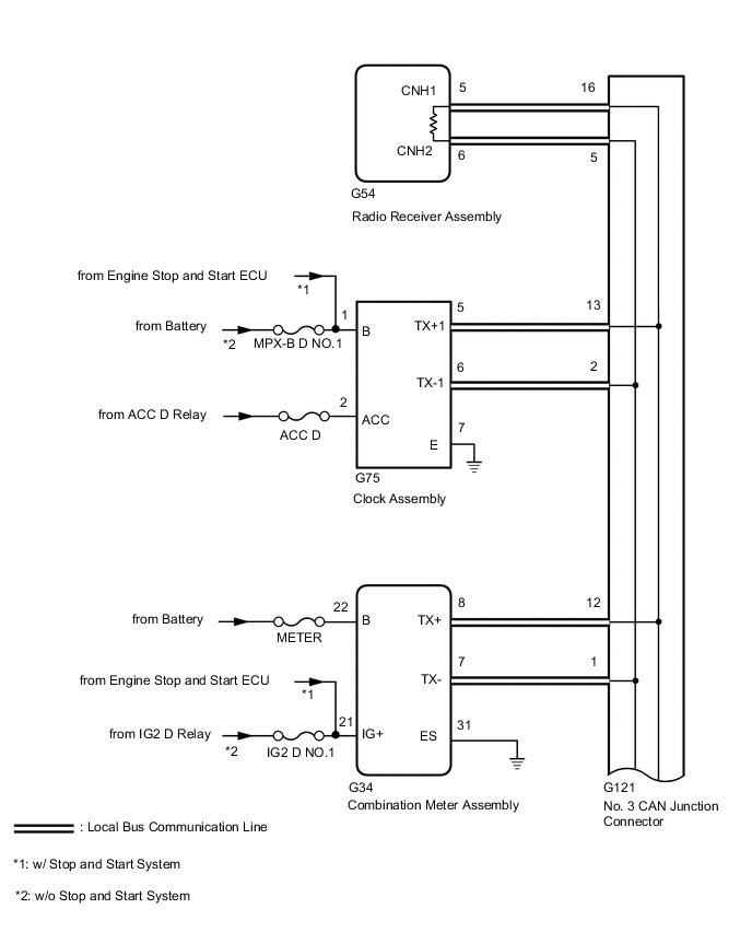
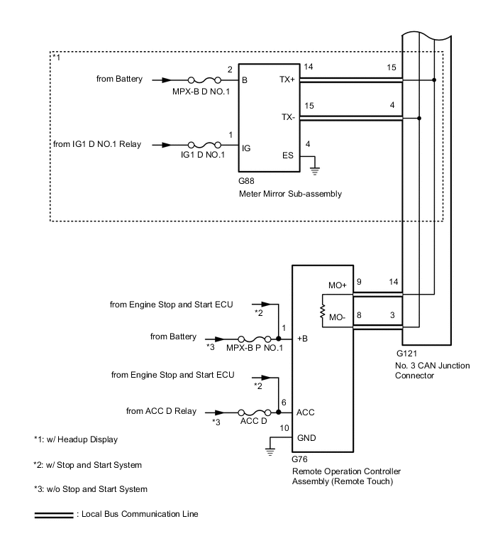
These DTCs are stored when communication between the radio receiver assembly and remote operation controller assembly (remote touch), combination meter assembly, meter mirror sub-assembly* or clock assembly is not possible.
-
*: w/ Headup Display
| DTC No. | Detection Item | DTC Detection Condition | Trouble Area |
|---|---|---|---|
| B1323 | Lost Communication with Haptic Device | CAN reception error |
|
| B1324 | Lost Communication with Meter | CAN reception error |
|
| B1325 | Lost Communication with HUD | CAN reception error |
|
| B1326 | Lost Communication with Clock Device (Local-CAN) | CAN reception error |
|
Tech Tips
The radio receiver assembly is the master unit.
WIRING DIAGRAM
CAUTION / NOTICE / HINT
Note
-
When replacing the radio receiver assembly, always replace it with a new one.
If a radio receiver assembly which was installed to another vehicle is used, the following may occur:
-
A communication malfunction DTC may be stored.
-
The radio receiver assembly may not operate normally.
-
After turning the engine switch off, waiting time may be required before disconnecting the cable from the negative (-) battery terminal. Therefore, make sure to read the disconnecting the cable from the negative (-) battery terminal notices before proceeding with work.
-
Inspect the fuses for circuits related to this system before performing the following procedure.
Tech Tips
Depending on the parts that are replaced during vehicle inspection or maintenance, performing initialization, registration or calibration may be needed. Refer to Precaution for Audio System.
PROCEDURE
-
CHECK DTC
-
Check for DTCs.
Body Electrical > Navigation System > Trouble CodesResult *: w/ Headup DisplayResult Proceed to DTCs B1323, B1324, B1325* and B1326 are output A DTC B1323 is output B DTC B1324 is output C DTCs B1325 is output* D DTC B1326 is output E
B 
CHECK HARNESS AND CONNECTOR (REMOTE OPERATION CONTROLLER ASSEMBLY [REMOTE TOUCH] POWER SOURCE) Click here
C
CHECK HARNESS AND CONNECTOR (COMBINATION METER ASSEMBLY POWER SOURCE) Click here
D
CHECK HARNESS AND CONNECTOR (METER MIRROR SUB-ASSEMBLY POWER SOURCE) Click here
E
CHECK HARNESS AND CONNECTOR (CLOCK ASSEMBLY POWER SOURCE) Click here
A 
-
-
CHECK LOCAL BUS
-
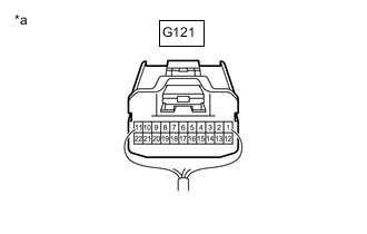
*a Rear view of wire harness connector
(No. 3 CAN Junction Connector)
Disconnect the cable from the negative (-) battery terminal.
-
Measure the resistance according to the value(s) in the table below.
Standard Resistance Tester Connection Condition Specified Condition G121-5 - G121-16 Cable disconnected from negative (-) battery terminal 54 to 69 Ω Result Result Proceed to OK A NG (Below 54 Ω) B NG (70 Ω or higher) C
A 
USE SIMULATION METHOD TO CHECK Click here
B
CHECK HARNESS AND CONNECTOR (NO. 3 CAN JUNCTION CONNECTOR - RADIO RECEIVER ASSEMBLY) Click here
C
CHECK HARNESS AND CONNECTOR (NO. 3 CAN JUNCTION CONNECTOR - RADIO RECEIVER ASSEMBLY) Click here
-
-
CHECK HARNESS AND CONNECTOR (REMOTE OPERATION CONTROLLER ASSEMBLY [REMOTE TOUCH] POWER SOURCE)
-
Disconnect the G76 remote operation controller assembly (remote touch) connector.
-
Measure the resistance according to the value(s) in the table below.
Standard Resistance Tester Connection Condition Specified Condition G76-10 (GND) - Body ground Always Below 1 Ω -
Measure the voltage according to the value(s) in the table below.
Standard Voltage *1: w/ Stop and Start SystemTester Connection Condition Specified Condition G76-1 (+B) - Body ground Always 10.5 to 16 V*1
11 to 14 V*2
G76-6 (ACC) - Body ground Engine switch on (ACC) 10.5 to 16 V*1
11 to 14 V*2
*2: w/o Stop and Start System
Result Proceed to OK NG
NG
REPAIR OR REPLACE HARNESS OR CONNECTOR
OK
-
-
CHECK HARNESS AND CONNECTOR (REMOTE OPERATION CONTROLLER ASSEMBLY [REMOTE TOUCH] - NO. 3 CAN JUNCTION CONNECTOR)
-
Disconnect the cable from the negative (-) battery terminal.
-
Disconnect the G76 remote operation controller assembly (remote touch) connector.
-
Measure the resistance according to the value(s) in the table below.
Standard Resistance Tester Connection Condition Specified Condition G76-9 (MO+) - G76-8 (MO-) Cable disconnected from negative (-) battery terminal 108 to 132 Ω Result Proceed to OK NG
OK
REPLACE REMOTE OPERATION CONTROLLER ASSEMBLY (REMOTE TOUCH) Click here
NG
REPAIR OR REPLACE HARNESS OR CONNECTOR
-
-
CHECK HARNESS AND CONNECTOR (NO. 3 CAN JUNCTION CONNECTOR - RADIO RECEIVER ASSEMBLY)
-
Disconnect the No. 3 CAN junction connector.
-

*a Rear view of wire harness connector
(No. 3 CAN Junction Connector)
Measure the resistance according to the value(s) in the table below.
Standard Resistance Tester Connection Condition Specified Condition G121-5 - G121-16 Cable disconnected from negative (-) battery terminal 108 to 132 Ω Result Proceed to OK NG
NG
CHECK HARNESS AND CONNECTOR (RADIO RECEIVER ASSEMBLY - NO. 3 CAN JUNCTION CONNECTOR) Click here
OK
-
-
CHECK HARNESS AND CONNECTOR (NO. 3 CAN JUNCTION CONNECTOR - REMOTE OPERATION CONTROLLER ASSEMBLY [REMOTE TOUCH])
-

*a Rear view of wire harness connector
(No. 3 CAN Junction Connector)
Disconnect the No. 3 CAN junction connector.
-
Measure the resistance according to the value(s) in the table below.
Standard Resistance Tester Connection Condition Specified Condition G121-3 - G121-14 Cable disconnected from negative (-) battery terminal 108 to 132 Ω Result Proceed to OK NG
NG
CHECK HARNESS AND CONNECTOR (REMOTE OPERATION CONTROLLER ASSEMBLY [REMOTE TOUCH] - NO. 3 CAN JUNCTION CONNECTOR) Click here
OK
-
-
CHECK HARNESS AND CONNECTOR (NO. 3 CAN JUNCTION CONNECTOR - COMBINATION METER ASSEMBLY)
-

*a Rear view of wire harness connector
(No. 3 CAN Junction Connector)
Disconnect the No. 3 CAN junction connector.
-
Measure the resistance according to the value(s) in the table below.
Standard Resistance Tester Connection Condition Specified Condition G121-1 - G121-12 Cable disconnected from negative (-) battery terminal 200 Ω or higher Result Proceed to OK NG
NG
CHECK HARNESS AND CONNECTOR (COMBINATION METER ASSEMBLY - NO. 3 CAN JUNCTION CONNECTOR) Click here
OK
-
-
CHECK VEHICLE TYPE
-
Check the vehicle type.
Result Result Proceed to w/ Headup Display A w/o Headup Display B
B
GO TO STEP 10 Click here
A
-
-
CHECK HARNESS AND CONNECTOR (NO. 3 CAN JUNCTION CONNECTOR - METER MIRROR SUB-ASSEMBLY)
-
Disconnect the No. 3 CAN junction connector.
-

*a Rear view of wire harness connector
(No. 3 CAN Junction Connector)
Measure the resistance according to the value(s) in the table below.
Standard Resistance Tester Connection Condition Specified Condition G121-4 - G121-15 Cable disconnected from negative (-) battery terminal 200 Ω or higher Result Proceed to OK NG
NG
CHECK HARNESS AND CONNECTOR (METER MIRROR SUB-ASSEMBLY - NO. 3 CAN JUNCTION CONNECTOR) Click here
OK
-
-
CHECK HARNESS AND CONNECTOR (NO. 3 CAN JUNCTION CONNECTOR - CLOCK ASSEMBLY)
-

*a Rear view of wire harness connector
(No. 3 CAN Junction Connector)
Disconnect the No. 3 CAN junction connector.
-
Measure the resistance according to the value(s) in the table below.
Standard Resistance Tester Connection Condition Specified Condition G121-2 - G121-13 Cable disconnected from negative (-) battery terminal 200 Ω or higher Result Proceed to OK NG
OK
REPLACE NO. 3 CAN JUNCTION CONNECTOR
NG
CHECK HARNESS AND CONNECTOR (CLOCK ASSEMBLY - NO. 3 CAN JUNCTION CONNECTOR) Click here
-
-
CHECK HARNESS AND CONNECTOR (RADIO RECEIVER ASSEMBLY - NO. 3 CAN JUNCTION CONNECTOR)
-
Disconnect the G54 radio receiver assembly connector.
-
Measure the resistance according to the value(s) in the table below.
Standard Resistance Tester Connection Condition Specified Condition G54-5 (CNH1) - G54-6 (CNL1) Cable disconnected from negative (-) battery terminal 108 to 132 Ω Result Proceed to OK NG
OK
REPLACE RADIO RECEIVER ASSEMBLY Click here
NG
REPAIR OR REPLACE HARNESS OR CONNECTOR
-
-
CHECK HARNESS AND CONNECTOR (REMOTE OPERATION CONTROLLER ASSEMBLY [REMOTE TOUCH] - NO. 3 CAN JUNCTION CONNECTOR)
-
Disconnect the G76 remote operation controller assembly (remote touch) connector.
-
Measure the resistance according to the value(s) in the table below.
Standard Resistance Tester Connection Condition Specified Condition G76-9 (MO+) - G76-8 (MO-) Cable disconnected from negative (-) battery terminal 108 to 132 Ω Result Proceed to OK NG
OK
REPLACE REMOTE OPERATION CONTROLLER ASSEMBLY (REMOTE TOUCH) Click here
NG
REPAIR OR REPLACE HARNESS OR CONNECTOR
-
-
CHECK HARNESS AND CONNECTOR (COMBINATION METER ASSEMBLY - NO. 3 CAN JUNCTION CONNECTOR)
-
Disconnect the G34 combination meter assembly connector.
-
Measure the resistance according to the value(s) in the table below.
Standard Resistance Tester Connection Condition Specified Condition G34-8 (TX+) - G34-7 (TX-) Cable disconnected from negative (-) battery terminal 54 to 69 Ω Result Proceed to OK NG
OK
REPLACE COMBINATION METER ASSEMBLY Click here
NG
REPAIR OR REPLACE HARNESS OR CONNECTOR
-
-
CHECK HARNESS AND CONNECTOR (METER MIRROR SUB-ASSEMBLY - NO. 3 CAN JUNCTION CONNECTOR)
-
Disconnect the G88 meter mirror sub-assembly connector.
-
Measure the resistance according to the value(s) in the table below.
Standard Resistance Tester Connection Condition Specified Condition G88-14 (TX+) - G88-15 (TX-) Cable disconnected from negative (-) battery terminal 54 to 69 Ω Result Proceed to OK NG
OK
REPLACE METER MIRROR SUB-ASSEMBLY Click here
NG
REPAIR OR REPLACE HARNESS OR CONNECTOR
-
-
CHECK HARNESS AND CONNECTOR (CLOCK ASSEMBLY - NO. 3 CAN JUNCTION CONNECTOR)
-
Disconnect the G75 clock assembly connector.
-
Measure the resistance according to the value(s) in the table below.
Standard Resistance Tester Connection Condition Specified Condition G75-5 (TX+1) - G75-6 (TX-1) Cable disconnected from negative (-) battery terminal 54 to 69 Ω Result Proceed to OK NG
OK
REPLACE CLOCK ASSEMBLY Click here
NG
REPAIR OR REPLACE HARNESS OR CONNECTOR
-
-
CHECK HARNESS AND CONNECTOR (COMBINATION METER ASSEMBLY POWER SOURCE)
-
Disconnect the G34 combination meter assembly connector.
-
Measure the resistance according to the value(s) in the table below.
Standard Resistance Tester Connection Condition Specified Condition G34-31 (ES) - Body ground Always Below 1 Ω -
Measure the voltage according to the value(s) in the table below.
Standard Voltage *1: w/ Stop and Start SystemTester Connection Condition Specified Condition G34-22 (B) - Body ground Always 11 to 14 V G34-21 (IG+) - Body ground Engine switch on (IG) 10.5 to 16 V*1
11 to 14 V*2
*2: w/o Stop and Start System
Result Proceed to OK NG
NG
REPAIR OR REPLACE HARNESS OR CONNECTOR
OK
-
-
CHECK HARNESS AND CONNECTOR (COMBINATION METER ASSEMBLY - NO. 3 CAN JUNCTION CONNECTOR)
-
Disconnect the cable from the negative (-) battery terminal.
-
Disconnect the G34 combination meter assembly connector.
-
Measure the resistance according to the value(s) in the table below.
Standard Resistance Tester Connection Condition Specified Condition G34-8 (TX+) - G34-7 (TX-) Cable disconnected from negative (-) battery terminal 54 to 69 Ω Result Proceed to OK NG
OK
REPLACE COMBINATION METER ASSEMBLY Click here
NG
REPAIR OR REPLACE HARNESS OR CONNECTOR
-
-
CHECK HARNESS AND CONNECTOR (NO. 3 CAN JUNCTION CONNECTOR - RADIO RECEIVER ASSEMBLY)
-
Disconnect the cable from the negative (-) battery terminal.
-
Disconnect the No. 3 CAN junction connector.
-

*a Rear view of wire harness connector
(No. 3 CAN Junction Connector)
Measure the resistance according to the value(s) in the table below.
Standard Resistance Tester Connection Condition Specified Condition G121-5 - G121-16 Cable disconnected from negative (-) battery terminal 108 to 132 Ω Result Proceed to OK NG
NG
CHECK HARNESS AND CONNECTOR (RADIO RECEIVER ASSEMBLY - NO. 3 CAN JUNCTION CONNECTOR) Click here
OK
-
-
CHECK HARNESS AND CONNECTOR (NO. 3 CAN JUNCTION CONNECTOR - REMOTE OPERATION CONTROLLER ASSEMBLY [REMOTE TOUCH])
-
Disconnect the cable from the negative (-) battery terminal.
-
Disconnect the No. 3 CAN junction connector.
-
*a Rear view of wire harness connector
(No. 3 CAN Junction Connector)0
Measure the resistance according to the value(s) in the table below.
Standard Resistance Tester Connection Condition Specified Condition G121-3 - G121-14 Cable disconnected from negative (-) battery terminal 108 to 132 Ω Result Proceed to OK NG
OK
REPLACE NO. 3 CAN JUNCTION CONNECTOR
NG
CHECK HARNESS AND CONNECTOR (REMOTE OPERATION CONTROLLER ASSEMBLY [REMOTE TOUCH] - NO. 3 CAN JUNCTION CONNECTOR) Click here
-
-
CHECK HARNESS AND CONNECTOR (METER MIRROR SUB-ASSEMBLY POWER SOURCE)
-
Disconnect the G88 meter mirror sub-assembly connector.
-
Measure the resistance according to the value(s) in the table below.
Standard Resistance Tester Connection Condition Specified Condition G88-4 (ES) - Body ground Always Below 1 Ω -
Measure the voltage according to the value(s) in the table below.
Standard Voltage Tester Connection Condition Specified Condition G88-2 (B) - Body ground Always 11 to 14 V G88-1 (IG) - Body ground Engine switch on (IG) 11 to 14 V Result Proceed to OK NG
NG
REPAIR OR REPLACE HARNESS OR CONNECTOR
OK
-
-
CHECK HARNESS AND CONNECTOR (METER MIRROR SUB-ASSEMBLY - NO. 3 CAN JUNCTION CONNECTOR)
-
Disconnect the cable from the negative (-) battery terminal.
-
Disconnect the G88 meter mirror sub-assembly connector.
-
Measure the resistance according to the value(s) in the table below.
Standard Resistance Tester Connection Condition Specified Condition G88-14 (TX+) - G88-15 (TX-) Cable disconnected from negative (-) battery terminal 54 to 69 Ω Result Proceed to OK NG
OK
REPLACE METER MIRROR SUB-ASSEMBLY Click here
NG
REPAIR OR REPLACE HARNESS OR CONNECTOR
-
-
CHECK HARNESS AND CONNECTOR (RADIO RECEIVER ASSEMBLY - NO. 3 CAN JUNCTION CONNECTOR)
-
Disconnect the G54 radio receiver assembly connector.
-
Measure the resistance according to the value(s) in the table below.
Standard Resistance Tester Connection Condition Specified Condition G54-5 (CNH1) - G54-6 (CNL1) Cable disconnected from negative (-) battery terminal 108 to 132 Ω Result Proceed to OK NG
OK
REPLACE RADIO RECEIVER ASSEMBLY Click here
NG
REPAIR OR REPLACE HARNESS OR CONNECTOR
-
-
CHECK HARNESS AND CONNECTOR (REMOTE OPERATION CONTROLLER ASSEMBLY [REMOTE TOUCH] - NO. 3 CAN JUNCTION CONNECTOR)
-
Disconnect the G76 remote operation controller assembly (remote touch) connector.
-
Measure the resistance according to the value(s) in the table below.
Standard Resistance Tester Connection Condition Specified Condition G76-9 (MO+) - G76-8 (MO-) Cable disconnected from negative (-) battery terminal 108 to 132 Ω Result Proceed to OK NG
OK
REPLACE REMOTE OPERATION CONTROLLER ASSEMBLY (REMOTE TOUCH) Click here
NG
REPAIR OR REPLACE HARNESS OR CONNECTOR
-
-
CHECK HARNESS AND CONNECTOR (CLOCK ASSEMBLY POWER SOURCE)
-
Disconnect the G75 clock assembly connector.
-
Measure the resistance according to the value(s) in the table below.
Standard Resistance Tester Connection Condition Specified Condition G75-7 (E) - Body ground Always Below 1 Ω -
Measure the voltage according to the value(s) in the table below.
Standard Voltage *1: w/ Stop and Start SystemTester Connection Condition Specified Condition G75-1 (B) - Body ground Always 10.5 to 16 V*1
11 to 14 V*2
G75-2 (ACC) - Body ground Engine switch on (ACC) 11 to 14 V
*2: w/o Stop and Start System
Result Proceed to OK NG
NG
REPAIR OR REPLACE HARNESS OR CONNECTOR
OK
-
-
CHECK HARNESS AND CONNECTOR (CLOCK ASSEMBLY - NO. 3 CAN JUNCTION CONNECTOR)
-
Disconnect the cable from the negative (-) battery terminal.
-
Disconnect the G75 clock assembly connector.
-
Measure the resistance according to the value(s) in the table below.
Standard Resistance Tester Connection Condition Specified Condition G75-5 (TX+1) - G75-6 (TX-1) Cable disconnected from negative (-) battery terminal 54 to 69 Ω Result Proceed to OK NG
OK
REPLACE CLOCK ASSEMBLY Click here
NG
REPAIR OR REPLACE HARNESS OR CONNECTOR
-