ECD SYSTEM (w/ EGR Cooler) MIL Circuit
DESCRIPTION
The MIL (Malfunction Indicator Lamp) is used to indicate vehicle malfunction detections by the ECM.
By turning the ignition switch ON, power is supplied to the MIL circuit, and the ECM provides the circuit ground which illuminates the MIL.
The MIL operation can be checked visually: When the ignition switch is first turned ON, the MIL should be illuminated and should then turn OFF. If the MIL remains illuminated or is not illuminated, conduct the following troubleshooting procedure using an intelligent tester.
WIRING DIAGRAM
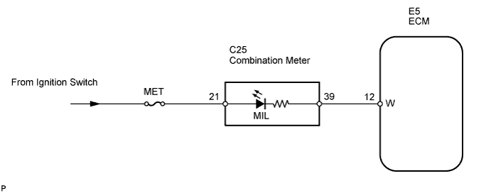
INSPECTION PROCEDURE
Note
If the ECM is replaced, the new ECM needs registration Click here and initialization Click here.
PROCEDURE
-
CHECK THAT MIL IS ILLUMINATED
-
Perform troubleshooting in accordance with the chart below.
Result MIL Condition Proceed to MIL remains ON A MIL does not illuminate B
B 
CHECK THAT MIL IS ILLUMINATED Click here
A 
-
-
CHECK WHETHER MIL TURNS OFF
-
Connect the intelligent tester to the DLC3.
-
Turn the ignition switch ON.
-
Turn the tester ON.
-
Check whether any DTCs have been stored. Note them down if necessary.
-
Clear DTCs Click here.
-
Check if the MIL turns off.
OK MIL should turn off.
OK 
DTC CHART
NG
-
-
CHECK HARNESS AND CONNECTOR (CHECK FOR SHORT IN WIRE HARNESS)
-
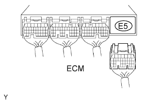
Disconnect the E5 ECM connector.
-
Turn the ignition switch ON.
-
Check that MIL is not illuminated.
OK MIL does not illuminate. -
Reconnect the ECM connector.
NG
CHECK HARNESS AND CONNECTOR (COMBINATION METER - ECM) Click here
OK 
REPLACE ECM
-
-
CHECK THAT MIL IS ILLUMINATED
-
Check if the MIL illuminated when the ignition switch is turns ON.
OK MIL should be illuminated.
OK
SYSTEM OK
NG
-
-
CHECK THAT ENGINE STARTS
-
Turn the ignition switch ON.
-
Start the engine.
Result Result Proceed To Engine starts A Engine does not start* B Tech Tips
*: An intelligent tester cannot communicate with the ECM.
B
GO TO VC OUTPUT CIRCUIT
A
-
-
CHECK HARNESS AND CONNECTOR (COMBINATION METER - ECM)
-
Disconnect the C25 combination meter connector.
-
Disconnect the E5 ECM connector.
-
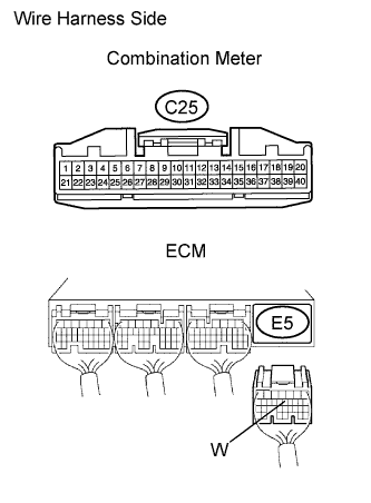
Measure the resistance of the wire harness side connectors.
Standard resistance (Check for open) Tester Connection Specified Condition C25-39 - W (E5-12) Below 1 Ω Standard resistance (Check for short) Tester Connection Specified Condition C25-39 or W (E5-12) - Body ground 10 kΩ or higher
NG
REPAIR OR REPLACE HARNESS OR CONNECTOR (COMBINATION METER - ECM)
OK
REPLACE COMBINATION METER ASSEMBLY
-