LUMBAR SUPPORT ADJUSTER ASSEMBLY REMOVAL
CAUTION / NOTICE / HINT
The necessary procedures (adjustment, calibration, initialization or registration) that must be performed after parts are removed and installed, or replaced during lumbar support adjuster assembly removal/installation are shown below.
| Replacement Part or Procedure | Necessary Procedures | Effects/Inoperative when not Performed | Link |
|---|---|---|---|
| Disconnect cable from negative battery terminal | Memorize steering angle neutral point | LKA /LDA system | |
| Intelligent clearance sonar system*1 | |||
| Pre-crash safety system | |||
| Lighting system (EXT)
|
|||
| Adaptive high beam system | |||
| Parking Assist Monitor System (w/ Parallel Parking Assist Function) | |||
| Parking Assist Monitor System (w/o Parallel Parking Assist Function) | |||
| Panoramic view monitor system | |||
| Drive the vehicle until stop and start control is permitted (approximately 15 to 60 minutes) | Stop and start system | ||
| Initialize back door lock | Power door lock control system | ||
| Reset back door close position | Power back door system | ||
| w/ occupant classification system
|
Zero point calibration (Occupant classification system) |
|
|
|
Initialize position control ECU | Front Power Seat Control System (w/ Memory) |
Click here Click here
CAUTION:
-
Be sure to read Precaution thoroughly before servicing.
-
Wear protective gloves. Sharp areas on the parts may injure your hands.
Tech Tips
-
Use the same procedure for the RH side and LH side.
-
The following procedure is for the LH side.
PROCEDURE
-
REMOVE FRONT SEAT ASSEMBLY
-
DISCONNECT FRONT SEATBACK BOARD SUB-ASSEMBLY
-
REMOVE FRONT SEAT CUSHION SHIELD (for Standard Seat Type)
-
REMOVE INNER NO. 1 FRONT SEAT CUSHION SHIELD (for Standard Seat Type)
-
REMOVE INNER NO. 1 FRONT SEAT CUSHION SHIELD (for Sports Seat Type)
-
REMOVE FRONT SEAT CUSHION SHIELD (for Sports Seat Type)
-
REMOVE FRONT SEAT INNER CUSHION SHIELD
-
REMOVE SEPARATE TYPE FRONT SEATBACK ASSEMBLY
-
REMOVE FRONT SEATBACK BOARD SUB-ASSEMBLY
-
REMOVE FRONT SEAT HEADREST SUPPORT
-
REMOVE SEPARATE TYPE FRONT SEATBACK COVER WITH PAD (for Standard Seat Type)
-
REMOVE FRONT SEATBACK PAD WITH COVER (for Sports Seat Type)
-
REMOVE TELEVISION BASE (w/ Rear Seat Entertainment System)
-
REMOVE SEATBACK FELT
-
REMOVE FRONT SEATBACK EDGE PROTECTOR
-
REMOVE LUMBAR SUPPORT ADJUSTER ASSEMBLY
-
w/o Variable Seat Cushion System:
-
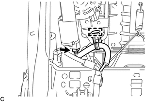
Disconnect the lumbar support adjuster assembly connector.
-
Disengage the clamp.
-
-
w/ Variable Seat Cushion System:
-
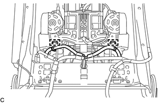
Disengage the 2 clamps.
-
Disconnect the 2 lumbar support adjuster assembly connectors.
-
-
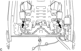
Disengage the 2 claws.
-
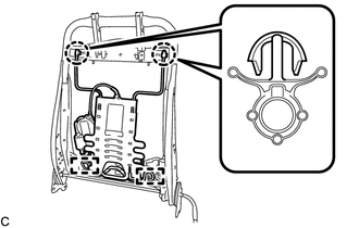
Disengage the 2 guides to remove the lumbar support adjuster assembly from the front seatback frame sub-assembly.
-
-
REMOVE FRONT SEATBACK HOOK