ENGINE UNIT INSTALLATION

CAUTION / NOTICE / HINT
Note
This procedure includes the installation of small-head bolts. Refer to Small-Head Bolts of Basic Repair Hint to identify the small-head bolts.
PROCEDURE
-
TEMPORARILY INSTALL FUEL PUMP ASSEMBLY (for Bank 2)
-
TEMPORARILY INSTALL NO. 2 FUEL PIPE SUB-ASSEMBLY
-
TIGHTEN FUEL PUMP ASSEMBLY (for Bank 2)
-
TIGHTEN NO. 2 FUEL PIPE SUB-ASSEMBLY
-
TEMPORARILY INSTALL FUEL PUMP ASSEMBLY (for Bank 1)
-
TEMPORARILY INSTALL NO. 1 FUEL PIPE SUB-ASSEMBLY
-
TIGHTEN FUEL PUMP ASSEMBLY (for Bank 1)
-
TIGHTEN NO. 1 FUEL PIPE SUB-ASSEMBLY
-
INSTALL V-RIBBED BELT TENSIONER ASSEMBLY
-
INSTALL IDLER PULLEY SUB-ASSEMBLY
-
INSTALL WATER PUMP PULLEY
-
INSTALL NO. 2 TURBO INSULATOR STAY
-
Install the No. 2 turbo insulator stay with the bolt.
- Torque:
- 21 N*m { 214 kgf*cm, 15 ft.*lbf }
-
-
INSTALL IGNITION COIL ASSEMBLY
-
INSTALL FUEL PIPE PROTECTOR BRACKET
-
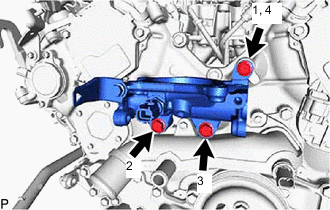
INSTALL NO. 1 WATER BY-PASS PIPE
-
Install the No. 1 water by-pass pipe with the 3 bolts.
- Torque:
- 21 N*m { 214 kgf*cm, 15 ft.*lbf }
-
-
INSTALL WATER OUTLET PIPE WATER BY-PASS JOINT
-
Install the water outlet pipe water by-pass joint with the 3 bolts in the order shown in the illustration.
- Torque:
- 21 N*m { 214 kgf*cm, 15 ft.*lbf }
-
-
INSTALL NO. 2 WATER OUTLET PIPE
-
Install 2 new gaskets to the No. 2 water outlet pipe.
-
Temporarily install the No. 2 water outlet pipe with the 4 bolts.
-
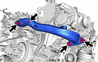
Tighten the 4 bolts in the order shown in the illustration.
- Torque:
- 21 N*m { 214 kgf*cm, 15 ft.*lbf }
-
-
INSTALL NO. 1 WATER OUTLET PIPE
-
Install 2 new gaskets to the No. 1 water outlet pipe.
-
Temporarily install the No. 1 water outlet pipe with the 4 bolts.
-
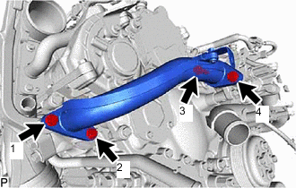
Tighten the 4 bolts in the order shown in the illustration.
- Torque:
- 21 N*m { 214 kgf*cm, 15 ft.*lbf }
-
-
INSTALL NO. 11 ENGINE WIRE
-
for Bank 1:
-
Remove the No. 11 engine wire to the No. 1 water outlet pipe with the bolt.
- Torque:
- 10 N*m { 102 kgf*cm, 7 ft.*lbf }
-
Connect the cam timing control motor with EDU assembly RH connector.
-
-
for Bank 2:
-
Connect the cam timing control motor with EDU assembly LH connector.
-
-
-
INSTALL NO. 2 WATER BY-PASS PIPE SUB-ASSEMBLY
-
Install the No. 2 water by-pass pipe sub-assembly with the 2 bolts.
- Torque:
- 10 N*m { 102 kgf*cm, 7 ft.*lbf }
-
-
INSTALL WATER CONTROL VALVE
-
INSTALL WATER HOSE (w/o Stop And Start System)
-
Connect the water hose to the water inlet assembly, and slide the 2 clips to secure the hose.
Note
Install the clip so that it faces the upper of the vehicle from the water hose.
-
-
INSTALL INTAKE PIPE STAY
-
INSTALL NO. 1 TURBO PRESSURE SENSOR
-
INSTALL INTAKE MANIFOLD
-
INSTALL FUEL HOSE PROTECTOR
-
INSTALL NO. 2 TURBO PRESSURE SENSOR (for Bank 2)
-
INSTALL NO. 2 TURBO PRESSURE SENSOR (for Bank 1)
-
INSTALL FUEL TUBE SUB-ASSEMBLY
-
INSTALL FUEL TUBE SUB-ASSEMBLY
-
INSTALL NO. 1 TURBO INSULATOR STAY
-
INSTALL NO. 5 ENGINE COVER
-
INSTALL NO. 4 ENGINE COVER
-
INSTALL NO. 5 TURBO INSULATOR
-
Install the No. 5 turbo insulator with the bolt.
- Torque:
- 21 N*m { 214 kgf*cm, 15 ft.*lbf }
-
-
INSTALL NO. 2 TURBOCHARGER SUB-ASSEMBLY
-
INSTALL NO. 1 TURBOCHARGER SUB-ASSEMBLY
-
INSTALL NO. 1 AIR HOSE
-
CONNECT VACUUM HOSE
-
CONNECT NO. 2 PCV TUBE
-
CONNECT NO. 1 PCV TUBE
-
INSTALL NO. 1 TURBO INSULATOR
-
INSTALL ENGINE OIL LEVEL DIPSTICK GUIDE
-
INSTALL NO. 1 VACUUM SWITCHING VALVE ASSEMBLY
-
INSTALL INTAKE AIR SURGE TANK ASSEMBLY WITH INTERCOOLER
-
INSTALL NO. 2 INTERCOOLER SUPPORT BRACKET
-
INSTALL INTERCOOLER SUPPORT BRACKET
-
INSTALL NO. 2 SURGE TANK STAY
-
INSTALL NO. 1 SURGE TANK STAY
-
INSTALL E.F.I. VACUUM SENSOR ASSEMBLY
-
INSTALL NO. 8 FUEL VAPOR FEED HOSE
-
INSTALL NO. 9 FUEL VAPOR FEED HOSE
-
INSTALL NO. 10 ENGINE WIRE
-
INSTALL NO. 9 ENGINE WIRE
-
INSTALL V-BANK COVER BRACKET
-
INSTALL FUEL VAPOR FEED PIPE
-
INSTALL SURGE TANK COVER
-
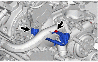
INSTALL NO. 2 WATER BY-PASS HOSE
-
Install the No. 2 water by-pass hose to the water control valve, and slide the clip to secure the hose.
-
-
INSTALL NO. 1 WATER BY-PASS TUBE
-
INSTALL THROTTLE BODY WITH MOTOR ASSEMBLY (for Bank 2)
-
INSTALL THROTTLE BODY WITH MOTOR ASSEMBLY (for Bank 1)
-
CONNECT NO. 2 AIR TUBE ASSEMBLY
-
CONNECT NO. 1 AIR TUBE ASSEMBLY