REAR SUNSHADE SYSTEM TERMINALS OF ECU
-
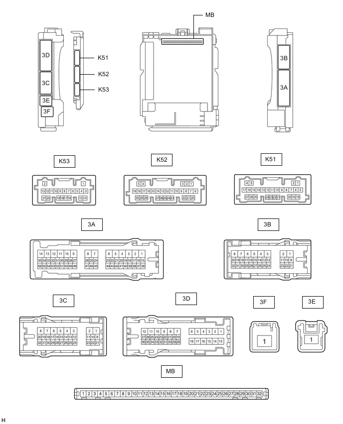
CHECK INSTRUMENT PANEL JUNCTION BLOCK ASSEMBLY AND MAIN BODY ECU (MULTIPLEX NETWORK BODY ECU)
-
Remove the main body ECU (multiplex network body ECU) from the instrument panel junction block assembly.
-
Reconnect the instrument panel junction block assembly connectors.
-
Measure the voltage and resistance according to the value(s) in the table below.
Tech Tips
Measure the values on the wire harness side with the connector disconnected.
Terminal No. (Symbol) Wiring Color Terminal Description Condition Specified Condition MB-11 (GND1) - Body ground - Ground Always Below 1 Ω MB-31 (BECU) - Body ground - Battery power supply Always 11 to 14 V MB-32 (IG) - Body ground - IG power supply Ignition switch off Below 1 V Ignition switch ON 11 to 14 V MB-30 (ACC) - Body ground - ACC power supply Ignition switch off Below 1 V Ignition switch ACC 11 to 14 V -
Install the main body ECU (multiplex network body ECU) to the instrument panel junction block assembly.
-
Measure the voltage according to the value(s) in the table below.
Terminal No. (Symbol) Wiring Color Terminal Description Condition Specified Condition K51-6 (REV) - Body ground B - Body ground Reverse signal Ignition switch ON, shift lever in any position other than R 11 to 14 V Ignition switch ON, shift lever in R Below 1 V
-
-
CHECK REAR WINDOW SHADE ASSEMBLY

-
Disconnect the R64 rear window shade assembly connector.
-
Measure the voltage and resistance according to the value(s) in the table below.
Tech Tips
Measure the values on the wire harness side with the connector disconnected.
Terminal No. (Symbol) Wiring Color Terminal Description Condition Specified Condition R64-8 (B) - Body ground LA-G - Body ground Battery power supply Always 11 to 14 V R64-7 (IG) - Body ground B - Body ground IG power supply Ignition switch off Below 1 V Ignition switch ON 11 to 14 V R64-1 (E) - Body ground LA - Body ground Ground Always Below 1 Ω -
Reconnect the R64 rear window shade assembly connector.
-
Measure the voltage according to the value(s) in the table below.
Terminal No. (Symbol) Wiring Color Terminal Description Condition Specified Condition R64-3 (REV) - R64-1 (E) LG - LA Reverse signal Ignition switch ON, shift lever in any position other than R 11 to 14 V Ignition switch ON, shift lever in R Below 1 V R64-5 (SW) - R64-1 (E) GR - LA Rear window shade assembly operation signal Procedure:
-
Ignition switch ON
-
Select Open or Close on the rear sunshade screen of the multi-information display.
5.5 V or higher → Below 1 V → 5.5 V or higher R64-4 (RSW) - R64-1 (E) BE - LA Rear window shade assembly operation signal Ignition switch ON, rear sunshade switch (cooler control switch assembly) not touched 5.5 V or higher Ignition switch ON, rear sunshade switch (cooler control switch assembly) touched 5.5 V or higher → Below 1 V → 5.5 V or higher -
-
-
CHECK COMBINATION METER ASSEMBLY
-
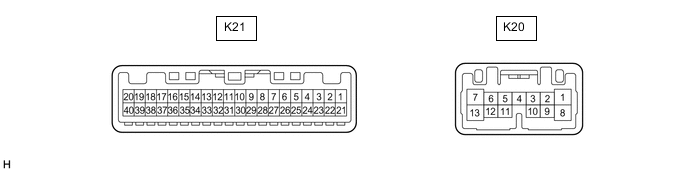
Disconnect the K21 combination meter assembly connector.
-
Measure the voltage and resistance according to the value(s) in the table below.
Tech Tips
Measure the values on the wire harness side with the connector disconnected.
Terminal No. (Symbol) Wiring Color Terminal Description Condition Specified Condition K21-40 (B) - Body ground LA-B - Body ground Battery power supply Always 11 to 14 V K21-39 (IG+) - Body ground LA-GR - Body ground IG power supply Ignition switch off Below 1 V Ignition switch ON 11 to 14 V K21-21 (ES) - Body ground W-B - Body ground Ground Always Below 1 Ω -
Reconnect the K21 combination meter assembly connector.
-
Measure the voltage according to the value(s) in the table below.
Terminal No. (Symbol) Wiring Color Terminal Description Condition Specified Condition K21-22 (ECU) - Body ground BE - Body ground Rear window shade assembly operation signal Procedure:
-
Ignition switch ON
-
Select Open or Close on the rear sunshade screen of the multi-information display.
5.5 V or higher → Below 1 V → 5.5 V or higher -
-