CYLINDER HEAD (for DPF) REMOVAL
Note
-
When replacing the injectors (including shuffling the injectors between the cylinders), common rail or cylinder head, it is necessary to replace the injection pipes with new ones.
-
When replacing the fuel supply pump, common rail, cylinder block, cylinder head, cylinder head gasket or timing gear case, it is necessary to replace the fuel inlet pipe with a new one.
-
After removing the injection pipes, clean them with a brush and compressed air.
-
DISCONNECT CABLE FROM NEGATIVE BATTERY TERMINAL
Note
When disconnecting the cable, some systems need to be initialized after the cable is reconnected Click here.
-
REMOVE NO. 1 ENGINE UNDER COVER SUB-ASSEMBLY
-
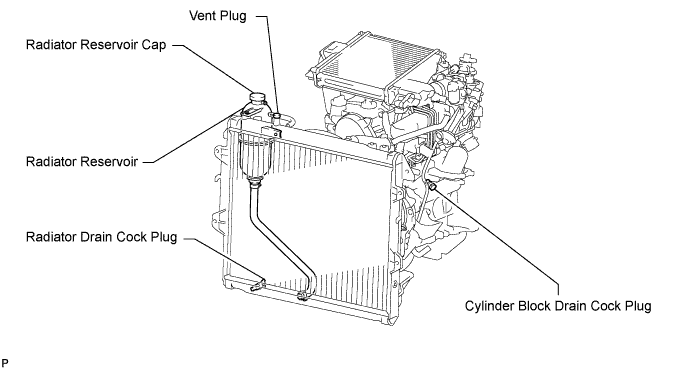
DRAIN ENGINE COOLANT
CAUTION:
Do not remove the radiator reservoir cap while the engine and radiator are still hot. Pressurized, hot engine coolant and steam may be released and cause serious burns.
-
Loosen the radiator drain cock plug.
Tech Tips
Collect the coolant in a container and dispose of it according to the regulations in your area.
-

Drain the coolant by removing the reservoir cap and, using a wrench, remove the vent plug.
-
Loosen the cylinder block drain cock plug.
-
-
DRAIN ENGINE OIL
-
Remove the oil filler cap.
-
Remove the oil pan drain plug and gasket, and then drain the engine oil into a container.
-
Wipe the oil pan and drain plug.
-
Install a new gasket and the oil pan drain plug.
- Torque:
- 34 N*m { 347 kgf*cm, 25 ft.*lbf }
-
-
REMOVE INTAKE MANIFOLD
-
REMOVE GLOW PLUG ASSEMBLY
-
REMOVE INJECTOR ASSEMBLY
-
REMOVE COMMON RAIL ASSEMBLY
-
REMOVE TURBOCHARGER SUB-ASSEMBLY
-
REMOVE FAN SHROUD
-
REMOVE VISCOUS HEATER WITH MAGNET CLUTCH ASSEMBLY (w/ Viscous Heater)
-
REMOVE NO. 1 VISCOUS HEATER BRACKET SUB-ASSEMBLY (w/ Viscous Heater)
-
Remove the 4 bolts and No. 1 viscous heater bracket.
-
-
DISCONNECT COOLER COMPRESSOR ASSEMBLY (w/ Air Conditioning System)
-
Remove the 4 bolts and disconnect the cooler compressor.
Tech Tips
It is not necessary to completely remove the cooler compressor. With the hoses connected to the cooler compressor, hang the cooler compressor on the vehicle body with a rope.
-
-
REMOVE NO. 1 COMPRESSOR MOUNTING BRACKET (w/ Air Conditioning System)
-
Remove the 4 bolts and No. 1 compressor mounting bracket.
-
-
REMOVE EXHAUST MANIFOLD
-
Remove the 8 nuts, 8 plate washers, 8 collars and exhaust manifold.
-
Remove the gasket.
-
-
REMOVE TIMING BELT
-
REMOVE CAMSHAFT TIMING PULLEY
-
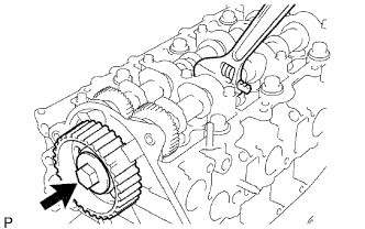
Remove the bolt of the camshaft timing pulley while holding the camshaft with a wrench.
Note
Make sure the timing belt is not installed when removing the bolt of the camshaft timing pulley.
-
Remove the camshaft timing pulley.
-
-
REMOVE NO. 2 TIMING BELT COVER
-
Remove the 4 bolts, nut and No. 2 timing belt cover.
-
-
REMOVE CYLINDER BLOCK INSULATOR
-
Remove the cylinder block insulator from the cylinder head.
-
-
REMOVE CAMSHAFT
-
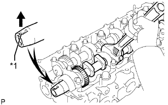
Text in Illustration *1 Key Groove Turn the camshaft with a wrench so that the key groove of the camshaft faces upward.
-
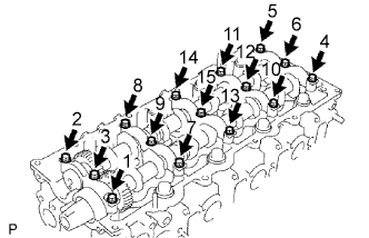
Uniformly loosen the 15 bearing cap bolts in several passes in the sequence shown in the illustration.
-
Remove the 15 bearing cap bolts, 5 bearing caps, oil seal and 2 camshafts.
-
-
REMOVE VALVE LIFTER
-
Remove the valve lifters.
Tech Tips
Arrange the valve lifters in the correct order.
-
-
REMOVE CYLINDER HEAD SUB-ASSEMBLY
-
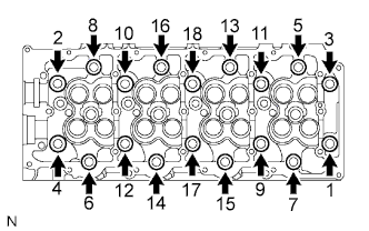
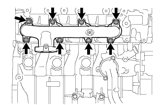
Uniformly loosen the 18 cylinder head bolts in several passes in the sequence shown in the illustration. Then remove the 18 cylinder head bolts and 18 washers.
Note
Head warpage or cracking could result from removing bolts in the incorrect order.
-
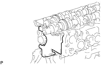
Remove the cylinder head from the dowels on the cylinder block and place the cylinder head on wooden blocks on a workbench.
Note
Be careful not to damage the contact surfaces of the cylinder head and cylinder block.
Tech Tips
If the cylinder head is difficult to remove, use a screwdriver to pry between the cylinder head and block.
-
-
REMOVE CYLINDER HEAD GASKET