WATER CONTROL VALVE INSTALLATION
CAUTION / NOTICE / HINT
Note
This procedure includes the installation of small-head bolts. Refer to Small-Head Bolts of Basic Repair Hint to identify the small-head bolts.
Tech Tips
-
Use the same procedure for RHD and LHD vehicles.
-
The procedure listed below is for LHD vehicles.
PROCEDURE
-
INSTALL WATER CONTROL VALVE
-
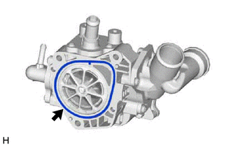
Install a new water outlet housing gasket to the water control valve.
-
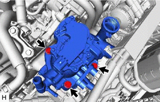
Install the water control valve with the 3 bolts.
- Torque:
- 21 N*m { 214 kgf*cm, 15 ft.*lbf }
-
-
INSTALL WATER FILLER CAP SUB-ASSEMBLY
-
Install the water filler cap sub-assembly to the water control valve.
-
-
CONNECT NO. 3 WATER BY-PASS HOSE
-
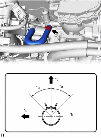
*a 45° *b Paint Mark *c Upper Side *d RH Side Connect the No. 3 water by-pass hose to the water control valve, and slide the clip to secure the hose.
Note
Align the direction of the claw on the clip with the paint mark on the hose.
-
-
CONNECT NO. 2 WATER BY-PASS HOSE
-
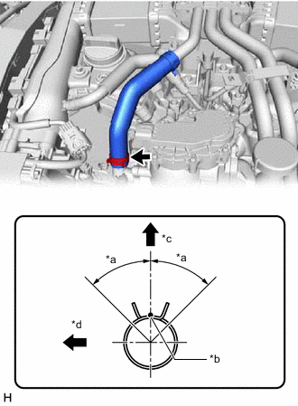
*a 45° *b Paint Mark *c Front Side *d RH Side Connect the No. 2 water by-pass hose to the water control valve, and slide the clip to secure the hose.
Note
Align the direction of the claw on the clip with the paint mark on the hose.
-
-
CONNECT NO. 1 WATER BY-PASS HOSE
-
Connect the No. 1 water by-pass hose to the water control valve, and slide the clip to secure the hose.
Note
-
Install so that the No. 1 water by-pass hose paint mark and water control valve positioning stopper are securely overlapped.
-
Make sure the No. 1 water by-pass hose is securely inserted to the stopper. (Axial Direction)
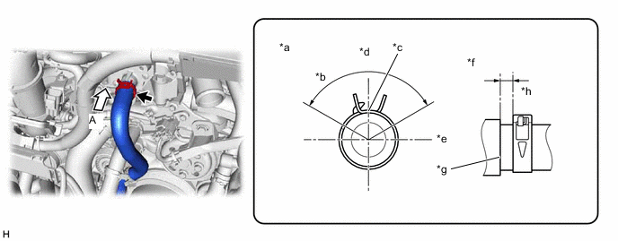
*a View A *b 120° *c Paint Mark *d Upper Side *e LH Side *f Axis Direction *g Stopper *h 2 to 7 mm (0.0787 to 0.276 in.) -
-
-
CONNECT NO. 3 RADIATOR HOSE
-
Connect the No. 3 radiator hose to the water control valve, and slide the clip to secure the hose.
Note
Install so that the No. 3 radiator hose paint mark and water inlet with thermostat sub-assembly positioning stopper are securely overlapped. (Rotational Direction)
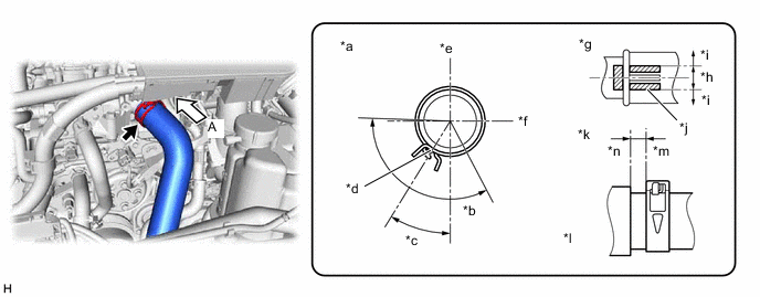
*a View A *b 120° *c 32.1° *d Paint Mark *e Upper Side *f LH Side *g Rotational Direction *h OK *i NG *j Variation Range *k Axis Direction *l Stopper *m 2 to 6 mm (0.0787 to 0.236 in.) *n 0 to 1 mm (0 to 0.0394 in.)
-
-
INSTALL INTAKE PIPE STAY
-
Install the intake pipe stay with the 2 bolts.
- Torque:
- 10 N*m { 102 kgf*cm, 7 ft.*lbf }
-
-
INSTALL NO. 1 TURBO PRESSURE SENSOR (for Bank 1)
-
CONNECT ENGINE WIRE
-
Connect the connectors and attach the clamps to connect the engine wire.
-
-
ADD ENGINE COOLANT
-
INSPECT FOR COOLANT LEAK
-
INSTALL LOWER RADIATOR AIR DEFLECTOR
-
INSTALL UPPER RADIATOR SUPPORT SEAL
-
INSTALL RADIATOR COVER PLATE
-
INSTALL V-BANK COVER SUB-ASSEMBLY
-
INSTALL STRUT BAR BRACKET SUPPORT SUB-ASSEMBLY (for AWD)
-
INSTALL FRONT SUSPENSION MEMBER BRACE (for AWD)
-
INSTALL OIL PAN PROTECTOR (for 2WD)
-
INSTALL NO. 1 ENGINE UNDER COVER ASSEMBLY
-
for 2WD:
-
for AWD:
-
-
CONNECT CABLE TO NEGATIVE BATTERY TERMINAL
Note
When disconnecting the cable, some systems need to be initialized after the cable is reconnected.
-
INSTALL LUGGAGE COMPARTMENT FLOOR MAT
-
INSTALL LUGGAGE COMPARTMENT MAT SUB-ASSEMBLY