VEHICLE STABILITY CONTROL SYSTEM ABS Warning Light Remains ON
DESCRIPTION
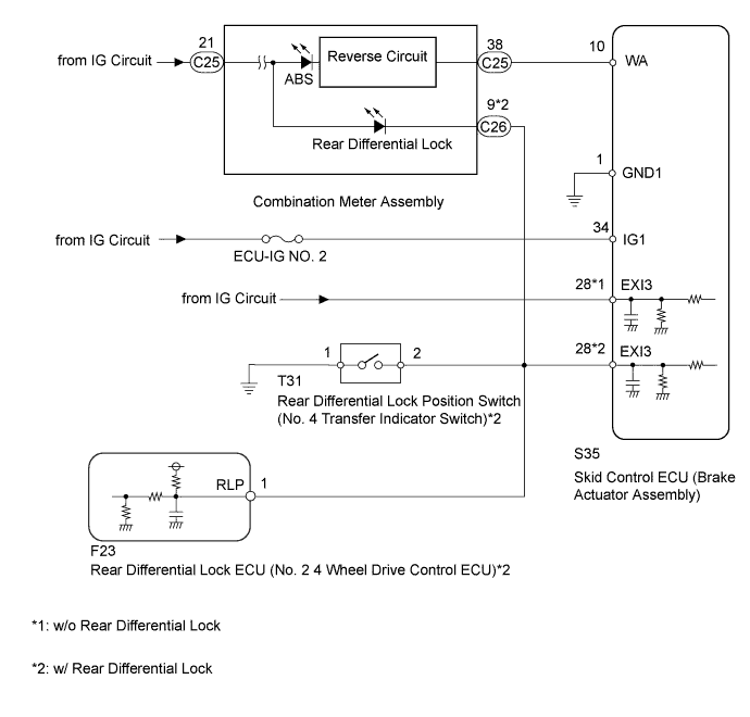
When one of the following conditions is met, the ABS warning light remains on:
-
The skid control ECU (brake actuator assembly) connector is disconnected from the skid control ECU.
-
There is a malfunction in the skid control ECU internal circuit.
-
There is an open in the harness between the combination meter and the skid control ECU.
-
The anti-lock brake system is defective.
-
w/ Rear Differential Lock:
The rear differential is locked.
WIRING DIAGRAM
INSPECTION PROCEDURE
Note
-
After replacing the brake actuator assembly, perform calibration Click here.
-
Inspect the fuses for circuits related to this system before performing the following inspection procedure.
-
Before disconnecting the connector, make sure that there are no problems with the connection.
-
After disconnecting the connector, make sure that the connector case and terminals are not deformed or corroded.
PROCEDURE
-
CHECK FOR DTC
-
Turn the ignition switch off.
-
Check if DTCs for the ABS are output Click here.
Result Result Proceed to DTC is not output A DTC is output B
B 
REPAIR CIRCUITS INDICATED BY OUTPUT DTCS Click here
A 
-
-
CHECK IF SKID CONTROL ECU CONNECTOR IS SECURELY CONNECTED
-
Check if the skid control ECU (brake actuator assembly) connector is securely connected.
OK The connector is securely connected.
NG
CONNECT CONNECTOR TO ECU CORRECTLY
OK
-
-
CHECK TERMINAL VOLTAGE (IG1 TERMINAL)
-
Turn the ignition switch off.
-
Disconnect the skid control ECU (brake actuator assembly) connector.
-
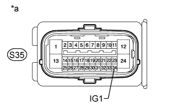
Text in Illustration *a Front view of wire harness connector
(to Skid Control ECU [Brake Actuator Assembly])
Measure the voltage according to the value(s) in the table below.
Standard Voltage Tester Connection Switch Condition Specified Condition S35-34 (IG1) - Body ground Ignition switch ON 11 to 14 V
NG
REPAIR OR REPLACE HARNESS OR CONNECTOR
OK
-
-
CHECK HARNESS AND CONNECTOR (GND1 TERMINAL)
-
Turn the ignition switch off.
-
Disconnect the skid control ECU (brake actuator assembly) connector.
-
Measure the resistance according to the value(s) in the table below.
Standard Resistance Tester Connection Condition Specified Condition S35-1 (GND1) - Body ground Always Below 1 Ω
NG
REPAIR OR REPLACE HARNESS OR CONNECTOR
OK
-
-
CHECK HARNESS AND CONNECTOR (SKID CONTROL ECU - COMBINATION METER)
-
Turn the ignition switch off.
-
Disconnect the skid control ECU (brake actuator assembly) connector.
-
Disconnect the C25 combination meter connector.
-
Measure the resistance according to the value(s) in the table below.
Standard Resistance Tester Connection Condition Specified Condition S35-10 (WA) - C25-38 Always Below 1 Ω S35-10 (WA) - Body ground Always 10 kΩ or higher
NG
REPAIR OR REPLACE HARNESS OR CONNECTOR
OK
-
-
CHECK TERMINAL VOLTAGE (EXI3 TERMINAL)
-
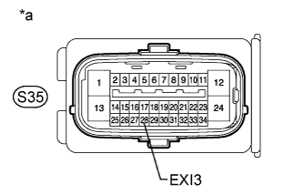
Text in Illustration *a Front view of wire harness connector
(to Skid Control ECU [Brake Actuator Assembly])
Turn the ignition switch off.
-
Disconnect the skid control ECU (brake actuator assembly) connector.
-
Measure the voltage according to the value(s) in the table below.
Standard Voltage Tester Connection Switch Condition Specified Condition S35-28 (EXI3) - Body ground Ignition switch ON 11 to 14 V Result Result Proceed to NG w/ Rear Differential Lock A w/o Rear Differential Lock B OK C
B
REPAIR OR REPLACE HARNESS OR CONNECTOR
C 
PERFORM ACTIVE TEST USING INTELLIGENT TESTER (ABS WARNING LIGHT) Click here
A
-
-
CHECK HARNESS AND CONNECTOR (EXI3 TERMINAL CIRCUIT)
-
Turn the ignition switch off.
-
Disconnect the rear differential lock position switch (No. 4 transfer indicator switch) connector.
-
Disconnect the rear differential lock ECU (No. 2 4 wheel drive control ECU) connector.
-
Disconnect the skid control ECU (brake actuator assembly) connector.
-
Disconnect the C26 combination meter connector.
-
Measure the resistance according to the value(s) in the table below.
Standard Resistance Tester Connection Condition Specified Condition S35-28 (EXI3) - T31-2 Always Below 1 Ω S35-28 (EXI3) - C26-9 Always Below 1 Ω S35-28 (EXI3) - F23-1 (RLP) Always Below 1 Ω S35-28 (EXI3) - Body ground Always 10 kΩ or higher
NG
REPAIR OR REPLACE HARNESS OR CONNECTOR
OK
-
-
INSPECT DIFFERENTIAL LOCK SYSTEM
-
Inspect rear differential lock system Click here.
NG
GO TO DIFFERENTIAL SYSTEM (PROBLEM SYMPTOMS TABLE) Click here
OK
-
-
PERFORM ACTIVE TEST USING INTELLIGENT TESTER (ABS WARNING LIGHT)
-
Turn the ignition switch off.
-
Connect the intelligent tester to the DLC3.
-
Turn the ignition switch to ON.
-
Turn the intelligent tester on.
-
Enter the following menus: Chassis / ABS/VSC/TRC / Active Test.
ABS/VSC/TRC Tester Display Test Part Control Range Diagnostic Note ABS Warning Light ABS warning light Warning light ON / OFF Observe the combination meter. -
When performing the ABS Warning Light Active Test, check ABS Warning Light in the Data List.
ABS/VSC/TRC Tester Display Measurement Item / Range Normal Condition Diagnostic Note ABS Warning Light ABS warning light /
ON or OFF
ON: ABS warning light on
OFF: ABS warning light off
- Result Result Proceed to Data List Display Data List Display When Performing Active Test ON/OFF Operation ON Does not change between ON and OFF for LHD A Does not change between ON and OFF for RHD B Changes between ON and OFF C OFF Does not change between ON and OFF for LHD A Does not change between ON and OFF for RHD B Changes between ON and OFF C
B
REPLACE BRAKE ACTUATOR ASSEMBLY Click here
C
GO TO METER / GAUGE SYSTEM (HOW TO PROCEED WITH TROUBLESHOOTING) Click here
A 
REPLACE BRAKE ACTUATOR ASSEMBLY Click here
-