VACUUM WARNING SWITCH ON-VEHICLE INSPECTION
PROCEDURE
-
REMOVE UPPER RADIATOR SUPPORT SEAL (for LHD)
-
REMOVE RADIATOR COVER PLATE (for RHD)
-
REMOVE FENDER APRON BRACE SUB-ASSEMBLY LH (for LHD)
-
REMOVE FENDER APRON BRACE SUB-ASSEMBLY RH (for RHD)
-
INSPECT BRAKE FLUID LEVEL IN RESERVOIR
-
INSPECT BRAKE BOOSTER ASSEMBLY
-
for LHD: Click here
-
for RHD: Click here
-
-
INSPECT VACUUM WARNING SWITCH ASSEMBLY
-
Start the engine and stop it after 1 or 2 minutes.
-
Disconnect the connector from the vacuum warning switch assembly.
-
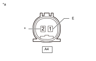
*a Component without harness connected
(Vacuum Warning Switch Assembly)
Measure the resistance according to the value(s) in the table below.
Standard Resistance Tester Connection Specified Condition A4-1 (E) - A4-2 (+) 10 kΩ or higher -
With the engine stopped, depress the brake pedal several times to release vacuum from the brake booster assembly, and measure the resistance of the vacuum warning switch assembly.
Standard Resistance Tester Connection Specified Condition A4-1 (E) - A4-2 (+) Below 1 Ω -
Connect the connector to the vacuum warning switch assembly.
-
-
INSTALL FENDER APRON BRACE SUB-ASSEMBLY LH (for LHD)
-
INSTALL FENDER APRON BRACE SUB-ASSEMBLY RH (for RHD)
-
INSTALL UPPER RADIATOR SUPPORT SEAL (for LHD)
-
INSTALL RADIATOR COVER PLATE (for RHD)