АВТОМАТИЧЕСКАЯ ТРАНСМИССИЯ В СБОРЕ УСТАНОВКА
-
INSPECT TORQUE CONVERTER CLUTCH ASSEMBLY
-
Inspect the torque converter clutch Click here.
-
-
INSTALL TORQUE CONVERTER CLUTCH ASSEMBLY
-
Install the torque converter clutch to the automatic transmission.
-
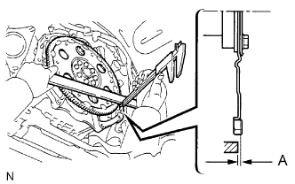
Using a vernier caliper and straightedge, measure dimension A between the transmission and the end surface of the drive plate.
Standard A = 22.28 mm (0.8772 in.) -
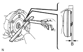
Using a vernier caliper and straightedge, measure dimension B shown in the illustration. Check that B is greater than A.
Standard B = A + 1.00 mm (0.0394 in.) or more
-
-
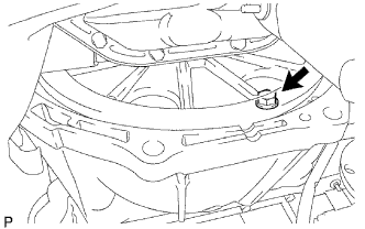
INSTALL NO. 1 ENGINE MOUNTING INSULATOR REAR
-
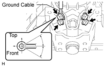
Install the engine mounting insulator and ground cable to the transmission with the 4 bolts.
- Torque:
- 47 N*m { 479 kgf*cm, 35 ft.*lbf }
Tech Tips
The acceptable installation angle of the ground cable is within 30° upward or downward from the horizontal position.
-
-
INSTALL AUTOMATIC TRANSMISSION ASSEMBLY
-
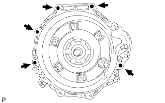
Install the transmission to the engine with the 5 bolts.
- Torque:
- 71 N*m { 720 kgf*cm, 53 ft.*lbf }
-
Hold the crankshaft pulley bolt with a wrench and install the 6 torque converter clutch mounting bolts.
- Torque:
- 48 N*m { 489 kgf*cm, 35 ft.*lbf }
-
-
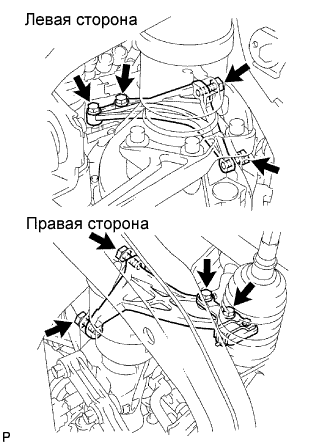
INSTALL STIFFENER PLATE
-
Install the No. 2 end plate.
-
Install the No. 4 cylinder block insulator.
-
Install the stiffener plate LH to the engine and transmission with the 4 bolts.
- Torque:
- 71 N*m { 720 kgf*cm, 53 ft.*lbf }
-
Install the stiffener plate RH (with clamp tube) to the engine and transmission with the 4 bolts.
- Torque:
- 71 N*m { 720 kgf*cm, 53 ft.*lbf }
-
-
CONNECT WIRE HARNESS
-
CONNECT CONNECTOR
-
Connect the connectors.
-
Connect the temperature sensor connector.
-
Connect the park/neutral position switch connector.
-
Connect the 3 speed sensor connectors.
-
Connect the transmission wire connector.
-
-
-
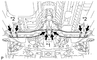
INSTALL NO. 3 FRAME CROSSMEMBER SUB-ASSEMBLY
-
*1: Install the 4 set bolts of the engine mounting insulator.
- Torque:
- 27 N*m { 275 kgf*cm, 20 ft.*lbf }
-
*2: Install the frame crossmember with the 4 bolts and 4 nuts.
- Torque:
- 50 N*m { 510 kgf*cm, 37 ft.*lbf }
-
-
INSTALL STARTER ASSEMBLY
-
Install the starter Click here.
-
-
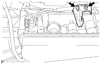
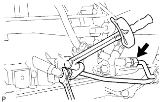
INSTALL TRANSMISSION CONTROL CABLE BRACKET
-
Install the control cable bracket with the 2 bolts.
- Torque:
- 28 N*m { 286 kgf*cm, 21 ft.*lbf }
-
-
CONNECT TRANSMISSION CONTROL SHIFT CABLE ASSEMBLY
-
Connect the control cable with the clip.
-
Connect the control cable with the nut.
- Torque:
- 14 N*m { 143 kgf*cm, 10 ft.*lbf }
-
-
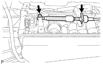
INSTALL OIL COOLER TUBE

-
Loosely install the tip of the oil cooler tube inlet to the automatic transmission by hand.
-
Loosely install the tip of the oil cooler tube outlet to the automatic transmission by hand.
-
Install the 3 clamps with the 3 bolts.
- Torque:
- 5.0 N*m { 51 kgf*cm, 43 in.*lbf, for A and B }
- 12 N*m { 122 kgf*cm, 9 ft.*lbf, for C }
-
Using a union nut wrench, disconnect the inlet tube and outlet tube.
- Torque:
- 34 N*m { 350 kgf*cm, 25 ft.*lbf }
Note
Use the formula to calculate special torque values for situations where a union nut wrench is combined with a torque wrench Click here
-
-
INSTALL TRANSMISSION OIL FILLER TUBE SUB-ASSEMBLY
-
Coat a new O-ring with ATF, and install it to the oil filler tube.
-
Install the oil filler tube with the 2 bolts.
- Torque:
- 12 N*m { 122 kgf*cm, 9 ft.*lbf }
-
Install the oil dipstick.
-
-
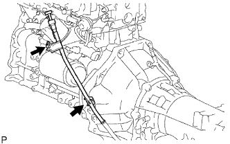
INSTALL PROPELLER SHAFT WITH CENTER BEARING ASSEMBLY
-
Install the propeller shaft with center bearing Click here.
-
-
INSTALL FRONT EXHAUST PIPE ASSEMBLY
-
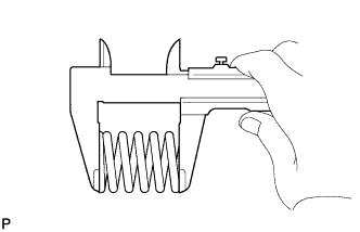
При помощи штангенциркуля замерьте длину пружины сжатия в свободном состоянии.
Минимально допустимая длина 40 мм (1,57 дюйма) Если длина в свободном состоянии меньше минимально допустимой, замените пружину сжатия.
-
Установите переднюю трубу на опору.
-
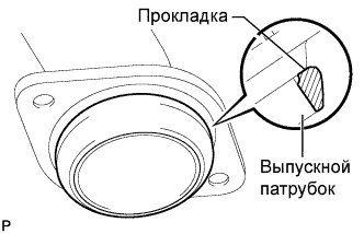
Установите на выпускную трубу новую прокладку.
Note
-
Правильно выберите направление установки прокладки.
-
Повторное использование прокладок запрещено.
-
Чтобы обеспечить надежное уплотнение, не насаживайте прокладку на выпускную трубу с помощью передней трубы.
Tech Tips
Наденьте прокладку на выпускную трубу, равномерно обстукивая прокладку пластмассовым молотком.
-
-
Установите переднюю трубу и закрепите ее 2 пружинами сжатия и 2 болтами. Поочередно затяните гайки в несколько этапов.
- Torque:
- 43 Н*м { 438 кгс*см, 32 фунт-сила-фута }
CAUTION:
Повторное использование прокладок запрещено.
-
-
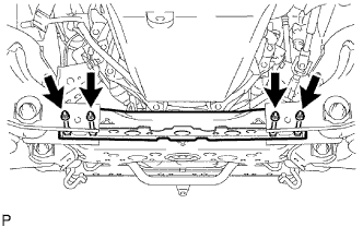
INSTALL NO. 2 FRAME CROSSMEMBER SUB-ASSEMBLY
-
Install the frame crossmember with the 4 bolts and 4 nuts.
- Torque:
- 50 N*m { 510 kgf*cm, 37 ft.*lbf }
-
-
ADJUST SHIFT LEVER POSITION
-
Adjust the shift lever position Click here.
-
-
ADD AUTOMATIC TRANSMISSION FLUID
Fluid type Toyota Genuine ATF TYPE T-IV -
CONNECT CABLE TO NEGATIVE BATTERY TERMINAL
-
PERFORM INITIALIZATION
-
Perform initialization Click here.
Note
Certain systems need to be initialized after disconnecting and reconnecting the cable from the negative (-) battery terminal.
-
-
INSPECT SHIFT LEVER POSITION
-
Inspect the shift lever position Click here.
-
-
CHECK FOR EXHAUST GAS LEAKS
-
CHECK AUTOMATIC TRANSMISSION FLUID
-
Inspect the automatic transmission fluid Click here.
-
-
INSTALL NO.2 ENGINE UNDER COVER
-
Установите защиту картера двигателя № 2 и закрепите ее 2 болтами.
- Torque:
- 28 Н*м { 286 кгс*см, 21 фунт-сила-фут }
-
-
INSTALL NO.1 ENGINE UNDER COVER
-
Установите защиту картера двигателя № 1 и закрепите ее 4 болтами.
- Torque:
- 28 Н*м { 286 кгс*см, 21 фунт-сила-фут }
-