INSTRUMENT PANEL SAFETY PAD REMOVAL
CAUTION / NOTICE / HINT
The necessary procedures (adjustment, calibration, initialization or registration) that must be performed after parts are removed and installed, or replaced during instrument panel safety pad removal/installation are shown below.
| Replaced Part or Performed Procedure | Necessary Procedure | Effect/Inoperative Function when Necessary Procedure not Performed | Link |
|---|---|---|---|
| Disconnect cable from negative battery terminal | Perform steering sensor zero point calibration | Lane departure alert system (w/ Steering Control) | |
| Pre-collision system | |||
| Memorize steering angle neutral point | Parking assist monitor system | ||
| Panoramic View Monitor System |
CAUTION:
Some of these service operations affect the SRS airbag system. Read the precautionary notices concerning the SRS airbag system before servicing.
PROCEDURE
-
PRECAUTION
Note
After turning the ignition switch off, waiting time may be required before disconnecting the cable from the negative (-) battery terminal. Therefore, make sure to read the disconnecting the cable from the negative (-) battery terminal notices before proceeding with work.
-
CHANGE POWER TILT AND POWER TELESCOPIC STEERING COLUMN SYSTEM SETTINGS (for Power Tilt and Power Telescopic Steering Column)
-
ALIGN FRONT WHEELS FACING STRAIGHT AHEAD
-
REMOVE HORN BUTTON ASSEMBLY
-
REMOVE STEERING WHEEL ASSEMBLY
-
REMOVE LOWER STEERING COLUMN COVER SUB-ASSEMBLY (for Manual Tilt and Manual Telescopic Steering Column)
-
REMOVE LOWER STEERING COLUMN COVER SUB-ASSEMBLY (for Power Tilt and Power Telescopic Steering Column)
-
REMOVE UPPER STEERING COLUMN COVER (for Manual Tilt and Manual Telescopic Steering Column)
-
REMOVE UPPER STEERING COLUMN COVER (for Power Tilt and Power Telescopic Steering Column)
-
REMOVE WINDSHIELD WIPER SWITCH ASSEMBLY
-
REMOVE TURN SIGNAL SWITCH
-
REMOVE CONSOLE BOX ASSEMBLY
-
REMOVE FRONT DOOR SCUFF PLATE LH
-
REMOVE COWL SIDE TRIM SUB-ASSEMBLY LH
-
DISCONNECT FRONT DOOR OPENING TRIM WEATHERSTRIP LH
-
Disconnect the front door opening trim weatherstrip LH.
-
-
REMOVE FRONT PILLAR GARNISH LH (w/o Curtain Shield Airbag)
-
REMOVE FRONT PILLAR GARNISH LH (w/ Curtain Shield Airbag)
-
REMOVE INSTRUMENT SIDE PANEL LH
-
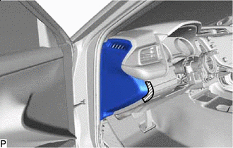

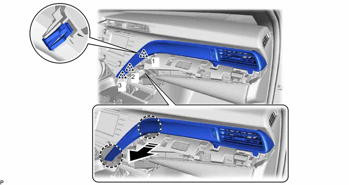
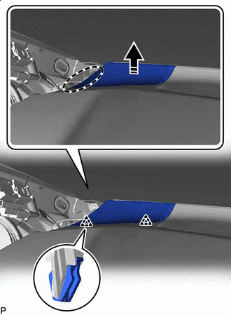
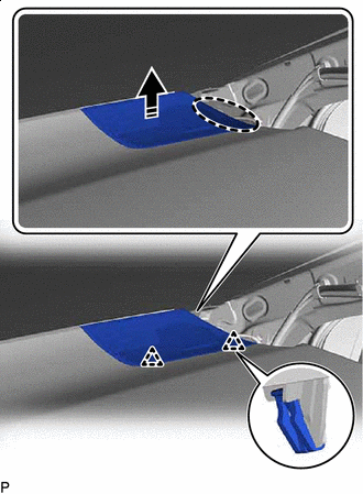
Protective Tape Apply protective tape to the area shown in the illustration.
-
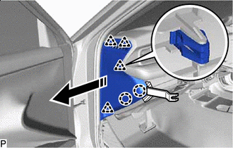

Remove in this Direction Using a moulding remover, disengage the 2 claws and 4 clips as shown in the illustration.
-
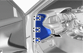
Remove in this Direction Disengage the 3 guides to remove the instrument side panel LH as shown in the illustration.
-
-
REMOVE NO. 1 INSTRUMENT PANEL UNDER COVER SUB-ASSEMBLY (for LHD)
-
Remove the 2 screws <C>.
-
Remove in this Direction Disengage the 3 claws as shown in the illustration.
-
Remove in this Direction Disengage the guide as shown in the illustration.
-
Disconnect the connector.
-
Disengage the 2 claws to disconnect the DLC3 connector.
-
Disengage the 2 clamps to remove the No. 1 instrument panel under cover sub-assembly.
-
-
REMOVE NO. 1 INSTRUMENT PANEL UNDER COVER SUB-ASSEMBLY (for RHD)
-
Remove the 3 screws <C>.
-
Remove in this Direction Disengage the 2 claws as shown in the illustration.
-
Disconnect the connector.
-
Disengage the 2 claws to disconnect the DLC3 connector.
-
Disengage the clamp to remove the No. 1 instrument panel under cover sub-assembly.
-
-
REMOVE NO. 2 METER HOOD CLUSTER
-

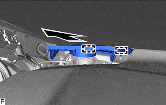
Place Hand Here Remove in this Direction Disengage the 3 clips to remove the No. 2 meter hood cluster as shown in the illustration.
-
-
DISCONNECT HOOD LOCK CONTROL LEVER SUB-ASSEMBLY
-
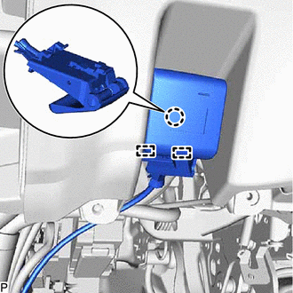
Disengage the claw and 2 guides to disconnect the hood lock control lever sub-assembly.
-
-
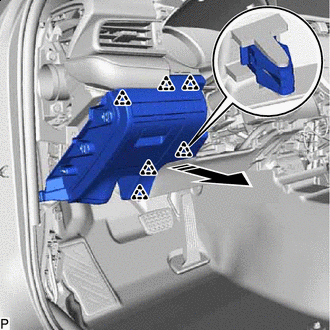
REMOVE NO. 1 INSTRUMENT PANEL SUB-ASSEMBLY (w/o Driver Side Knee Airbag)
-

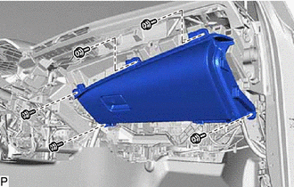
Remove in this Direction Disengage the 8 clips as shown in the illustration.
-
Disengage the clamp.
-
Disconnect each connector to remove the No. 1 instrument panel sub-assembly.
-
-
REMOVE NO. 1 INSTRUMENT PANEL SUB-ASSEMBLY (w/ Driver Side Knee Airbag)
-
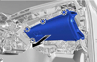
Remove in this Direction Disengage the 6 clips as shown in the illustration.
-
Disengage the clamp.
-
Disconnect each connector to remove the No. 1 instrument panel sub-assembly.
-
-
REMOVE LOWER NO. 1 INSTRUMENT PANEL AIRBAG ASSEMBLY (w/ Driver Side Knee Airbag)
for LHD:
for RHD:
-
REMOVE INSTRUMENT CLUSTER FINISH PANEL ASSEMBLY
-
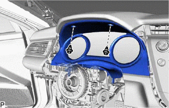
Remove the 2 clips.
-
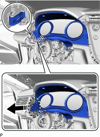
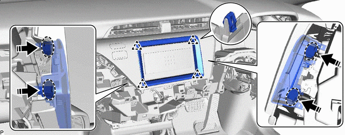
Place Hand Here Remove in this Direction Disengage the 2 clips as shown in the illustration.
-
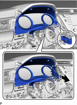
Place Hand Here Remove in this Direction Disengage the 2 clips as shown in the illustration.
-
Remove in this Direction Disengage the 2 guides as shown in the illustration.
-
Disconnect the connector to remove the instrument cluster finish panel assembly.
-
-
REMOVE COMBINATION METER ASSEMBLY
-
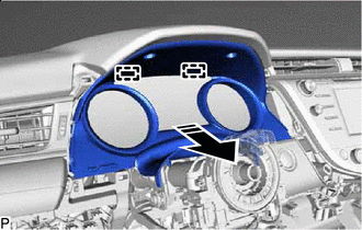
REMOVE LOWER INSTRUMENT PANEL FINISH PANEL ASSEMBLY
-
Place Hand Here Remove in this Direction Disengage the 5 clips to remove the lower instrument panel finish panel assembly as shown in the illustration.
-
w/ Switch:
-
Disconnect the connector.
-
-
-
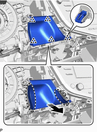
REMOVE NO. 3 INSTRUMENT PANEL REGISTER ASSEMBLY
-
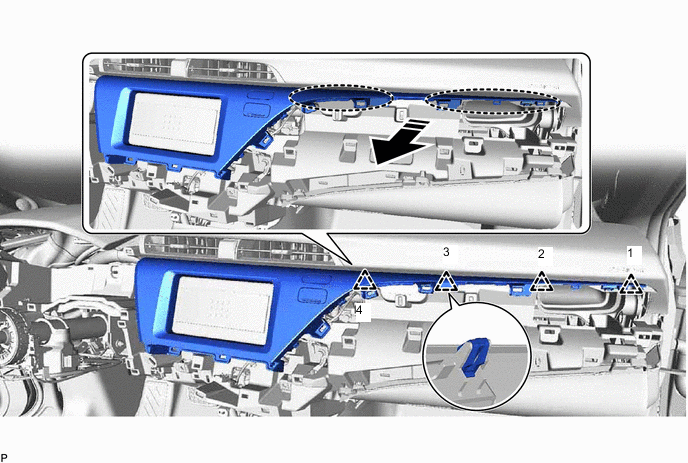
Disengage the 8 clips in the order shown in the illustration.
Place Hand Here Remove in this Direction -
Disengage the 3 clips in the order shown in the illustration.
Place Hand Here Remove in this Direction -
Disconnect the connector to remove the No. 3 instrument panel register assembly.
-
-
REMOVE AIR CONDITIONING CONTROL ASSEMBLY (except 8 Inch Display)
-
REMOVE INSTRUMENT CLUSTER FINISH PANEL COVER (w/o Radio Receiver)
-
for RHD:
-
Disengage the 4 clips to remove the instrument cluster finish panel cover as shown in the illustration.
Place Hand Here Remove in this Direction
-
-
-
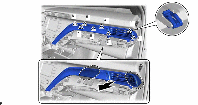
REMOVE CENTER INSTRUMENT CLUSTER FINISH PANEL ASSEMBLY (w/o Radio Receiver)
-
Disengage the 4 clips in the order shown in the illustration.
Place Hand Here Remove in this Direction -
Disengage the 5 clips as shown in the illustration.
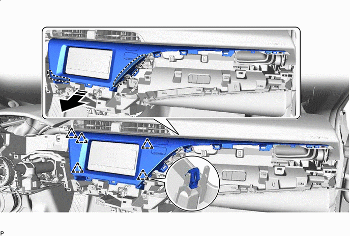
Place Hand Here Remove in this Direction -
Disconnect the connector to remove the center instrument cluster finish panel assembly.
-
-
REMOVE RADIO TUNER OPENING COVER WITH BRACKET (w/o Radio Receiver)
-
Remove the 4 bolts <B>.
-
Disconnect the connector to remove the radio tuner opening cover with bracket.
-
-
REMOVE RADIO RECEIVER ASSEMBLY WITH BRACKET (for Radio Receiver Type)
-
REMOVE RADIO AND DISPLAY RECEIVER ASSEMBLY WITH BRACKET (for Radio and Display Type)
for 7 Inch Display:
-
REMOVE RADIO AND DISPLAY RECEIVER ASSEMBLY WITH BRACKET (for Radio and Display Type)
for 8 Inch Display:
-
REMOVE FRONT DOOR SCUFF PLATE RH
Tech Tips
Use the same procedure as for the LH side.
-
REMOVE COWL SIDE TRIM SUB-ASSEMBLY RH
Tech Tips
Use the same procedure as for the LH side.
-
DISCONNECT FRONT DOOR OPENING TRIM WEATHERSTRIP RH
Tech Tips
Use the same procedure as for the LH side.
-
REMOVE FRONT PILLAR GARNISH RH
Tech Tips
Use the same procedure as for the LH side.
-
REMOVE INSTRUMENT SIDE PANEL RH
-
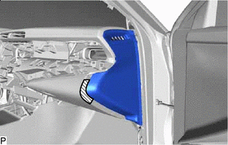
Protective Tape Apply protective tape to the area shown in the illustration.
-
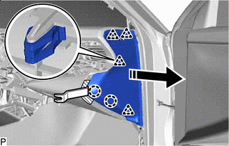
Remove in this Direction Using a moulding remover, disengage the 2 claws and 4 clips as shown in the illustration.
-
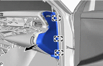
Remove in this Direction Disengage the 3 guides to remove the instrument side panel RH as shown in the illustration.
-
-
REMOVE NO. 2 INSTRUMENT PANEL UNDER COVER SUB-ASSEMBLY
-
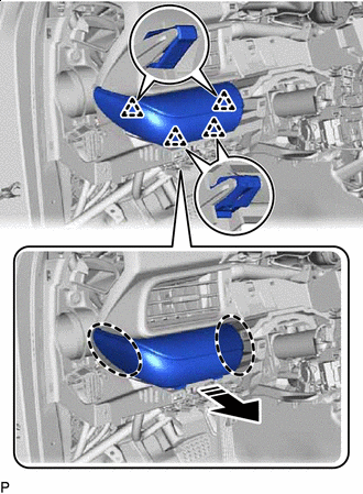
Remove in this Direction Disengage the 4 claws as shown in the illustration.
-
Remove in this Direction Disengage the 2 guides as shown in the illustration.
-
Disengage the clamp.
-
Disconnect the connector to remove the No. 2 instrument panel under cover sub-assembly.
-
-
REMOVE LOWER NO. 2 INSTRUMENT PANEL AIRBAG ASSEMBLY (w/ Passenger Side Knee Airbag)
-
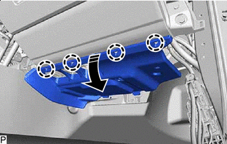
REMOVE LOWER INSTRUMENT PANEL SUB-ASSEMBLY (w/o Passenger Side Knee Airbag)
-
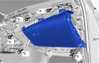
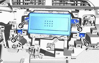
*a Screws <C> *b Bolts <D> Remove the 3 screws <C>.
-
Remove the 2 bolts <D>.
-
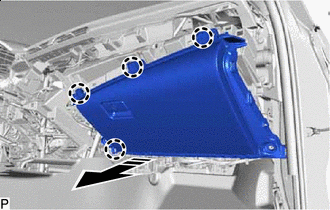
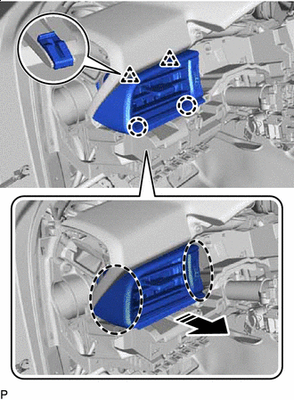
Remove in this Direction Disengage the 4 claws as shown in the illustration.
-
Disconnect the connector to remove the lower instrument panel sub-assembly.
-
-
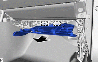
REMOVE LOWER INSTRUMENT PANEL SUB-ASSEMBLY (w/ Passenger Side Knee Airbag)
-
Remove the 5 screws <C>.
-
Remove in this Direction Disengage the 4 claws as shown in the illustration.
-
Disconnect the connector to remove the lower instrument panel sub-assembly.
-
-
REMOVE NO. 1 INSTRUMENT PANEL SPEAKER PANEL
-
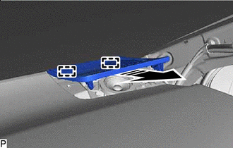
Place Hand Here Remove in this Direction Disengage the 2 clips as shown in the illustration.
-
Remove in this Direction Disengage the 2 guides to remove the No. 1 instrument panel speaker panel as shown in the illustration.
-
-
REMOVE FRONT NO. 2 SPEAKER ASSEMBLY (for LH Side)
-
REMOVE NO. 2 INSTRUMENT PANEL SPEAKER PANEL
-
Place Hand Here Remove in this Direction Disengage the 2 clips as shown in the illustration.
-
Remove in this Direction Disengage the 2 guides to remove the No. 2 instrument panel speaker panel as shown in the illustration.
-
-
REMOVE FRONT NO. 2 SPEAKER ASSEMBLY (for RH Side)
Tech Tips
Use the same procedure as for the LH side.
-
REMOVE NO. 1 INSTRUMENT PANEL GARNISH SUB-ASSEMBLY
-
Place Hand Here Remove in this Direction Disengage the 4 clips to remove the No. 1 instrument panel garnish sub-assembly as shown in the illustration.
-
-
REMOVE NO. 1 INSTRUMENT PANEL REGISTER ASSEMBLY
-
Place Hand Here Remove in this Direction Disengage the 2 clips and 2 claws to remove the No. 1 instrument panel register assembly as shown in the illustration.
-
-
DISCONNECT NO. 5 INSTRUMENT PANEL WIRE (w/o Occupant Classification System)
-
DISCONNECT NO. 5 INSTRUMENT PANEL WIRE (w/ Occupant Classification System)
-
REMOVE INSTRUMENT PANEL SAFETY PAD SUB-ASSEMBLY
-
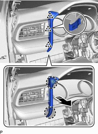
for Automatic Air Conditioning System:
-
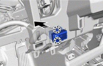
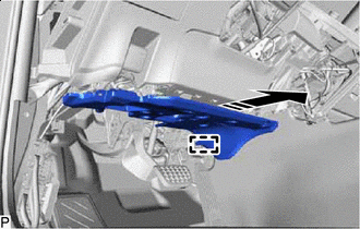
Remove in this Direction Disengage the 2 claws to disconnect the cooler (room temp. sensor) thermistor as shown in the illustration.
-
-
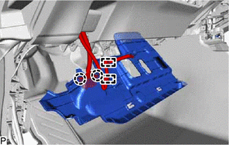
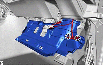
Disconnect each connector.
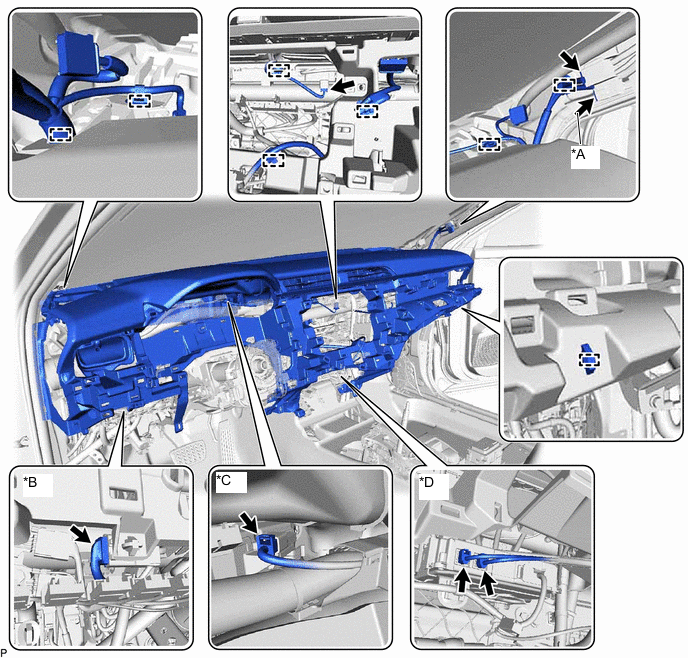
*A w/ Digital Audio Broadcasting Antenna, Television Antenna or Telematics Transceiver *B w/ Ion Generator *C w/ Headup Display *D w/ Telematics Transceiver -
Disengage each clamp.
-
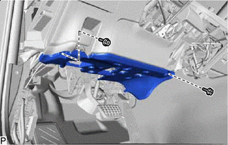
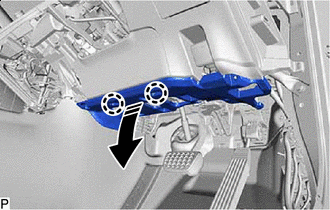
Remove the 2 clips.
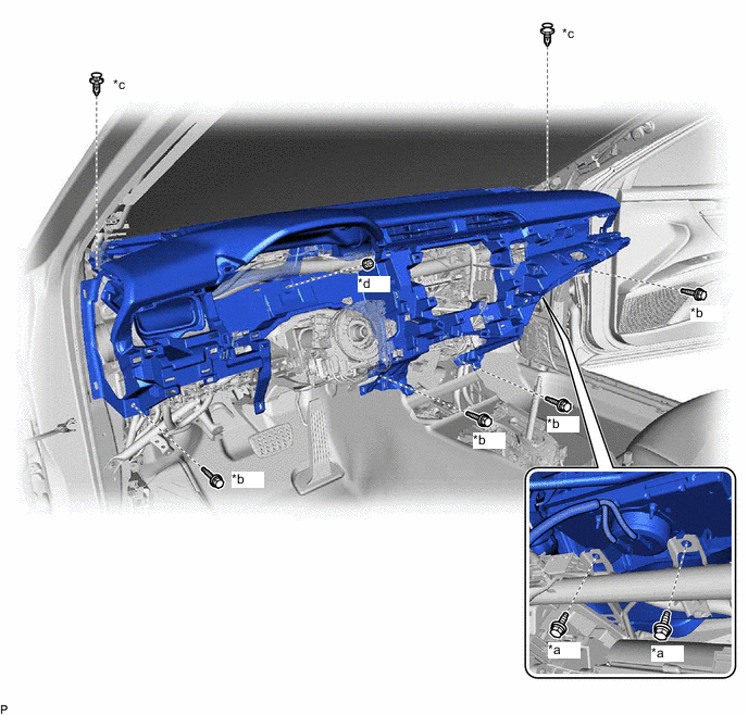
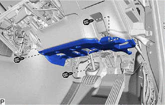
*a Bolt <A> *b Bolt <B> *c Clip *d Nut <F> -
Remove the 4 bolts <B>, 2 bolts <A> and nut <F>.
-
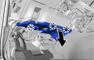
Disengage the 4 guides and remove the instrument panel safety pad sub-assembly as shown in the illustration.
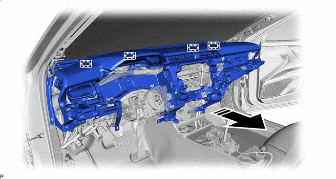
Remove in this Direction - - Note
-
Do not damage the instrument panel safety pad sub-assembly.
-
Do not allow the wire harnesses to interfere with the surrounding parts.
-
-