АВТОМАТИЧЕСКАЯ ТРАНСМИССИЯ В СБОРЕ УСТАНОВКА
-
INSTALL TRANSMISSION CONTROL CABLE BRACKET
-
Install the control cable bracket with the 2 bolts.
- Torque:
- 28 N*m { 286 kgf*cm, 21 ft.*lbf }
-
-
INSPECT TORQUE CONVERTER CLUTCH ASSEMBLY
-
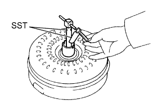
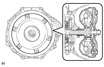
Inspect the one-way clutch.
-
Install SST in the inner race of the one-way clutch.
- SST
- 09350-32014 ( 09351-32010 )
-
Set SST so that it fits in the notch of the converter hub and in the outer race of the one-way clutch.
- SST
- 09350-32014 ( 09351-32020 )
-
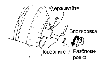
With the torque converter standing on its side, check that the clutch locks when SST is turned counterclockwise and rotates freely and smoothly when turned clockwise.
If the results are not as specified, clean the converter and recheck the one-way clutch.
If the results still are not as specified, replace the converter.
-
-
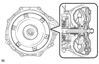
Determine the condition of the torque converter clutch.
-
Check that the following conditions are met:
-
During the stall test or when the shift lever is on N, metallic sounds are not emitted from the torque converter clutch.
-
The one-way clutch turns in one direction and locks in the other direction.
-
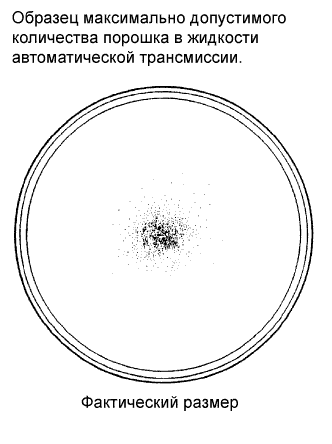
The amount of powder in the ATF is not greater than the sample shown in the illustration.
If the results are not as specified, replace the torque converter clutch assembly.
Tech Tips
The sample illustration shows approximately 0.25 liters (0.26 US qts, 0.22 Imp. qts) of the ATF taken from a removed torque converter clutch.
-
-
-
Replace the ATF in the torque converter clutch.
-
If the ATF is discolored and/or has a foul odor, stir the ATF in the torque converter clutch thoroughly and drain the ATF with the torque converter facing up.
-
-
Clean and check the oil cooler and oil pipe line.
-
If the torque converter clutch is inspected or the ATF is replaced, clean the oil cooler and oil pipe line.
Tech Tips
-
Apply compressed air of 196 kPa (2 kgf/cm2, 28 psi) into the inlet hose.
-
If a large amount of powder is found in the ATF, add new ATF using a bucket pump and clean the oil cooler and oil pipe line again.
-
-
If the ATF is cloudy, inspect the oil cooler (radiator).
-
-
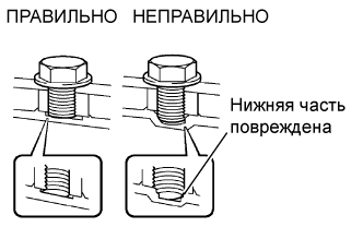
Prevent deformation of the torque converter clutch and damage to the oil pump gear.
-
When any marks due to interference are found on the end of the bolt for the torque converter clutch and on the bottom of the bolt hole, replace the bolt and torque converter clutch.
-
All of the bolts should be the same length.
-
Make sure no spring washers are missing.
-
-
-
INSTALL TORQUE CONVERTER CLUTCH ASSEMBLY
-
Engage the spline of the input shaft turbine runner.
-
Engage the spline of the stator shaft and the stator while turning the torque converter assembly.
Tech Tips
If the stator shaft splines are difficult to engage with the stator splines, move the torque converter back approximately 10 mm (0.394 in.) and engage the splines while rotating the torque converter.
-
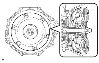
Turn the torque converter assembly to insert the key of the oil pump drive gear into the groove of the torque converter assembly.
-
Clean the torque converter set bolt holes.
-
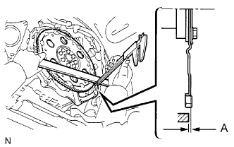
Using a vernier caliper and straightedge, measure dimension A between the transmission contact surface of the engine and the torque converter contact surface of the drive plate.
Note
Make sure to deduct the thickness of the straightedge.
-
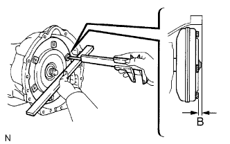
Using a vernier caliper and straightedge, measure dimension B shown in the illustration and check that dimension B is more than dimension A, which was measured in the previous step.
Standard B = A + 1.00 mm (0.0394 in.) or more Note
-
Make sure to deduct the thickness of the straightedge.
-
If the transaxle is installed to the engine with the torque converter not sufficiently inserted, the torque converter may be damaged.
-
-
-
INSTALL AUTOMATIC TRANSMISSION ASSEMBLY
-
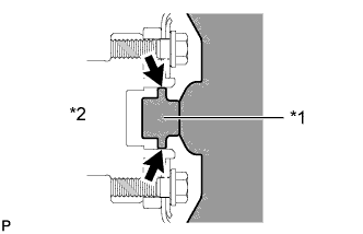
Text in Illustration *1 Torque Converter Centerpiece *2 Crankshaft Apply clutch spline grease to the surface of the crankshaft that contacts the torque converter centerpiece.
Clutch spline grease Toyota Genuine Clutch Spline Grease or equivalent Maximum grease amount Approximately 1 g (0.0353 oz.) -
While keeping the engine and automatic transmission assembly horizontal, align the knock pins with the holes in the automatic transmission assembly and Install the 5 bolts.
- Torque:
- 71 N*m { 720 kgf*cm, 53 ft.*lbf }
Note
-
Confirm that the 2 knock pins are installed to the transmission contact surface of the engine cylinder block before installing the automatic transmission assembly.
-
Do not forcibly pry on the automatic transmission assembly.
-
Check that the torque converter rotates.
-
-
INSTALL DRIVE PLATE AND TORQUE CONVERTER SETTING BOLT
-
Turn the crankshaft to gain access to the installation locations of the 6 drive plate torque converter setting bolts and install each bolt while holding the crankshaft pulley bolt with a wrench.
- Torque:
- 48 N*m { 489 kgf*cm, 35 ft.*lbf }
Note
First install the black colored bolt and then the remaining 5 silver colored bolts.
-
-
INSTALL STIFFENER PLATE
-
Install the No. 2 end plate.
-
Install the No. 4 cylinder block insulator.
-
Install the stiffener plate LH to the engine and transmission with the 4 bolts.
- Torque:
- 71 N*m { 720 kgf*cm, 53 ft.*lbf }
-
Install the stiffener plate RH (with clamp tube) to the engine and transmission with the 4 bolts.
- Torque:
- 71 N*m { 720 kgf*cm, 53 ft.*lbf }
-
-
CONNECT WIRE HARNESS CLAMP BRACKET
-
Install the wire harness clamp bracket with the bolt.
- Torque:
- 13 N*m { 128 kgf*cm, 9 ft.*lbf }
-
-
CONNECT ENGINE WIRE
-
Connect the connectors.
-
Connect the temperature sensor connector.
-
Connect the park/neutral position switch connector.
-
Connect the 3 speed sensor connectors.
-
Connect the transmission wire connector.
-
-
-
INSTALL REAR NO. 1 ENGINE MOUNTING INSULATOR
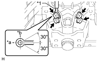
Text in Illustration *1 Ground Cable *a Front *b Upper
-
Install the engine mounting insulator and ground cable to the transmission with the 4 bolts.
- Torque:
- 47 N*m { 479 kgf*cm, 35 ft.*lbf }
Tech Tips
The acceptable installation angle of the ground cable is within 30° upward or downward from the horizontal position.
-
-
INSTALL NO. 3 FRAME CROSSMEMBER SUB-ASSEMBLY
-
Install the 4 set bolts of the engine mounting insulator.
- Torque:
- 27 N*m { 275 kgf*cm, 20 ft.*lbf }
-
Install the frame crossmember with the 4 bolts and 4 nuts.
- Torque:
- 50 N*m { 510 kgf*cm, 37 ft.*lbf }
-
-
INSTALL STARTER ASSEMBLY
-
CONNECT TRANSMISSION CONTROL SHIFT CABLE ASSEMBLY
-
Connect the control cable with the new clip.
-
Connect the control cable with the nut.
- Torque:
- 14 N*m { 143 kgf*cm, 10 ft.*lbf }
-
-
INSTALL OIL COOLER TUBE

-
Loosely install the tip of the oil cooler tube inlet to the automatic transmission by hand.
-
Loosely install the tip of the oil cooler tube outlet to the automatic transmission by hand.
-
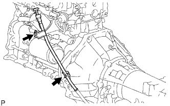
Install the 3 clamps with the 3 bolts.
- Torque:
- for Bolt A and B
- 5.0 N*m { 51 kgf*cm, 44 in.*lbf }
- for Bolt C
- 12 N*m { 122 kgf*cm, 9 ft.*lbf }
-
Using a union nut wrench, disconnect the inlet tube and outlet tube.
- Torque:
- 34 N*m { 350 kgf*cm, 25 ft.*lbf }
Note
Use the formula to calculate special torque values for situations where a union nut wrench is combined with a torque wrench Click here.
-
-
INSTALL TRANSMISSION OIL FILLER TUBE SUB-ASSEMBLY
-
Coat a new O-ring with ATF, and install it to the oil filler tube.
-
Install the oil filler tube with the 2 bolts.
- Torque:
- 12 N*m { 122 kgf*cm, 9 ft.*lbf }
-
Install the oil dipstick.
-
-
INSTALL PROPELLER SHAFT WITH CENTER BEARING ASSEMBLY
-
INSTALL FRONT EXHAUST PIPE ASSEMBLY
-
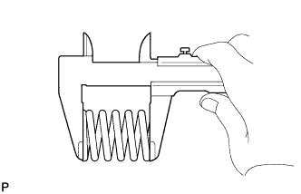
При помощи штангенциркуля замерьте длину пружины сжатия в свободном состоянии.
Минимально допустимая длина 40 мм (1,57 дюйма) Если длина в свободном состоянии меньше минимально допустимой, замените пружину сжатия.
-
Установите переднюю трубу на опору.
-
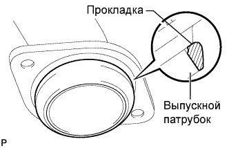
Установите на выпускную трубу новую прокладку.
Note
-
Правильно выберите направление установки прокладки.
-
Повторное использование прокладок запрещено.
-
Чтобы обеспечить надежное уплотнение, не насаживайте прокладку на выпускную трубу с помощью передней трубы.
Tech Tips
Наденьте прокладку на выпускную трубу, равномерно обстукивая прокладку пластмассовым молотком.
-
-
Установите переднюю трубу и закрепите ее 2 пружинами сжатия и 2 болтами. Поочередно затяните гайки в несколько этапов.
- Torque:
- 43 Н*м { 438 кгс*см, 32 фунт-сила-фута }
CAUTION:
Повторное использование прокладок запрещено.
-
-
INSTALL NO. 2 FRAME CROSSMEMBER SUB-ASSEMBLY (except Pre-Runner)
-
Install the frame crossmember with the 4 bolts and 4 nuts.
- Torque:
- 50 N*m { 510 kgf*cm, 37 ft.*lbf }
-
-
ADJUST SHIFT LEVER POSITION
-
ADD AUTOMATIC TRANSMISSION FLUID
Fluid type Toyota Genuine ATF TYPE T-IV -
CONNECT CABLE TO NEGATIVE BATTERY TERMINAL
Note
When disconnecting the cable, some systems need to be initialized after the cable is reconnected Click here.
-
INSPECT SHIFT LEVER POSITION
-
CHECK FOR EXHAUST GAS LEAKS
-
CHECK AUTOMATIC TRANSMISSION FLUID
-
INSTALL NO. 2 ENGINE UNDER COVER (for Pre-Runner)
- Torque:
- 28 Н*м { 286 кгс*см, 21 фунт-сила-фут }
-
INSTALL NO. 1 ENGINE UNDER COVER (for Pre-Runner)
- Torque:
- 28 Н*м { 286 кгс*см, 21 фунт-сила-фут }