LOAD SENSING PROPORTIONING VALVE (w/o VSC) INSTALLATION
-
INSTALL LOAD SENSING PROPORTIONING VALVE ASSEMBLY
-
Install the valve with the 3 bolts.
- Torque:
- 29 N*m { 300 kgf*cm, 22 ft.*lbf }
-
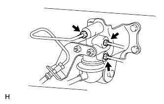
Using a union nut wrench, connect the 3 brake lines to the valve body.
- Torque:
- 15 N*m { 155 kgf*cm, 11 ft.*lbf }
Note
Use the formula to calculate special torque values for situations where a union nut wrench is combined with a torque wrench Click here.
-
-
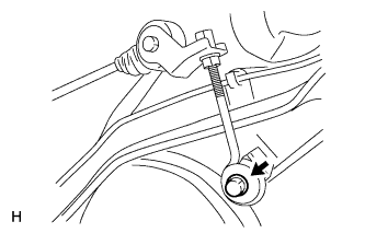
CONNECT NO. 2 LOAD SENSING SPRING SHACKLE
-
Connect the No. 2 shackle to the rear differential.
-
Install the bolt, collar and 2 bushes.
- Torque:
- 29 N*m { 300 kgf*cm, 22 ft.*lbf }
-
-
FILL RESERVOIR WITH BRAKE FLUID (for TMT Made)
Fluid SAE J1703 or FMVSS No. 116 DOT 3 -
FILL RESERVOIR WITH BRAKE FLUID (for TSAM Made)
Fluid SAE J1704 or FMVSS No. 116 DOT 4 -
BLEED AIR FROM BRAKE MASTER CYLINDER (for TMT Made)
Tech Tips
If the master cylinder has been disassembled or if the reservoir becomes empty, bleed air from the master cylinder.
-
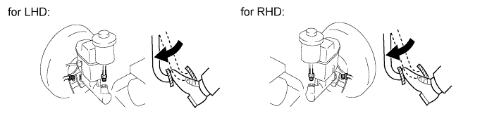
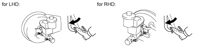
Using a union nut wrench, disconnect the 2 brake lines from the master cylinder.
-
Slowly depress and hold the brake pedal.
-
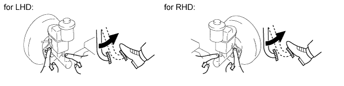
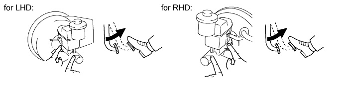
Cover the outer holes with your finger, and release the pedal.
-
Repeat the 2 previous steps 3 or 4 times.
-
Using a union nut wrench, connect the 2 brake lines to the master cylinder.
- Torque:
- 15 N*m { 155 kgf*cm, 11 ft.*lbf }
Note
Use the formula to calculate special torque values for situations where a union nut wrench is combined with a torque wrench Click here.
-
-
BLEED AIR FROM BRAKE MASTER CYLINDER (for TSAM Made)
Tech Tips
If the master cylinder has been disassembled or if the reservoir becomes empty, bleed air from the master cylinder.
-
Using a union nut wrench, disconnect the 2 brake lines from the master cylinder.
-
Slowly depress and hold the brake pedal.
-
Cover the outer holes with your finger, and release the pedal.
-
Repeat the 2 previous steps 3 or 4 times.
-
Using a union nut wrench, connect the 2 brake lines to the master cylinder.
- Torque:
- 15 N*m { 155 kgf*cm, 11 ft.*lbf }
Note
Use the formula to calculate special torque values for situations where a union nut wrench is combined with a torque wrench Click here.
-
-
BLEED AIR FROM LOAD SENSING VALVE BODY (for TMT Made)
-
Remove the bleeder plug cap.
-
Connect the vinyl tube to the bleeder plug.
-
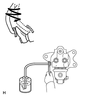
Depress the pedal several times, and then loosen the bleeder plug with the pedal depressed.
-
When fluid stops coming out, immediately tighten the bleeder plug. Then release the pedal.
-
Repeat the 2 previous steps until all the air in the brake fluid is gone.
-
Tighten the bleeder plug.
- Torque:
- 11 N*m { 107 kgf*cm, 8 ft.*lbf }
-
Install the bleeder plug cap.
-
-
BLEED AIR FROM LOAD SENSING VALVE BODY (for TSAM Made)
-
Remove the bleeder plug cap.
-
Connect the vinyl tube to the bleeder plug.
-
Depress the pedal several times, and then loosen the bleeder plug with the pedal depressed.
-
When fluid stops coming out, immediately tighten the bleeder plug. Then release the pedal.
-
Repeat the 2 previous steps until all the air in the brake fluid is gone.
-
Tighten the bleeder plug.
- Torque:
- 11 N*m { 107 kgf*cm, 8 ft.*lbf }
-
Install the bleeder plug cap.
-
-
BLEED AIR FROM BRAKE LINE (for TMT Made)
-
Remove the bleeder plug cap.
-
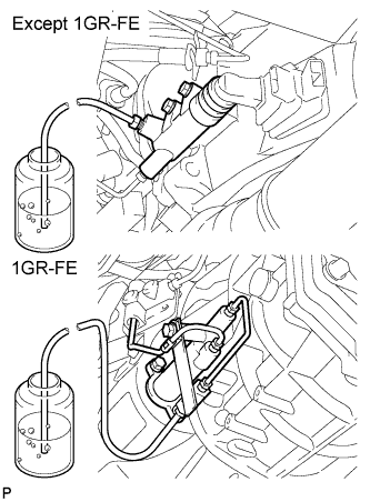
Connect the vinyl tube to the bleeder plugs.
-
Depress the pedal several times, and then loosen the bleeder plug with the pedal depressed.
-
When fluid stops coming out, immediately tighten the bleeder plug. Then release the pedal.
-
Repeat the 2 previous steps until all the air in the brake fluid is gone.
-
Tighten the bleeder plug.
- Torque:
- for front brake
- 11 N*m { 110 kgf*cm, 8 ft.*lbf }
- for rear brake (2WD)
- 11 N*m { 112 kgf*cm, 8 ft.*lbf }
- for rear brake (4WD and Pre-Runner)
- 10 N*m { 102 kgf*cm, 7 ft.*lbf }
-
Install the cap.
-
Bleed air from the brake line for each wheel by repeating the above procedures.
-
-
BLEED AIR FROM BRAKE LINE (for TSAM Made)
-
Remove the bleeder plug cap.
-
Connect the vinyl tube to the bleeder plugs.
-
Depress the pedal several times, and then loosen the bleeder plug with the pedal depressed.
-
When fluid stops coming out, immediately tighten the bleeder plug. Then release the pedal.
-
Repeat the 2 previous steps until all the air in the brake fluid is gone.
-
Tighten the bleeder plug.
- Torque:
- for front brake (2WD)
- 10 N*m { 102 kgf*cm, 7 ft.*lbf }
- for front brake (4WD and Pre-Runner)
- 11 N*m { 110 kgf*cm, 8 ft.*lbf }
- for rear brake (2WD)
- 11 N*m { 112 kgf*cm, 8 ft.*lbf }
- for rear brake (4WD and Pre-Runner)
- 10 N*m { 102 kgf*cm, 7 ft.*lbf }
-
Install the cap.
-
Bleed air from the brake line for each wheel by repeating the above procedures.
-
-
BLEED AIR FROM CLUTCH LINE (for Manual Transmission)
-
Remove the bleeder plug cap.
-
Connect the vinyl tube to the bleeder plug.
-
Depress the clutch pedal several times, and then loosen the bleeder plug with the pedal depressed.
-
At the point when fluid stops coming out, tighten the bleeder plug, and then release the clutch pedal.
-
Repeat the previous 2 steps until all the air in the fluid is completely bled out.
-
Tighten the bleeder plug.
- Torque:
- 11 N*m { 112 kgf*cm, 8 ft.*lbf }
-
Install the bleeder plug cap.
-
Check that all the air has been bled out of the clutch line.
-
-
CHECK BRAKE FLUID LEVEL IN RESERVOIR (for TMT Made)
-
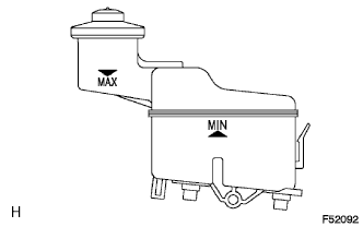
Check the fluid level.
If the brake fluid level is lower that the MIN line, check for leaks and inspect the disc brake pads. If necessary, refill the reservoir with brake fluid to the MAX line after repair or replacement.
Fluid SAE J1703 or FMVSS No. 116 DOT 3
-
-
CHECK BRAKE FLUID LEVEL IN RESERVOIR (for TSAM Made)
-
Check the fluid level.
If the brake fluid level is lower than the MIN line, check for leaks and inspect the disc brake pads. If necessary, refill the reservoir with brake fluid to the MAX line after repair or replacement.
Fluid SAE J1704 or FMVSS No. 116 DOT 4
-
-
CHECK FOR BRAKE FLUID LEAKAGE
-
CHECK LOAD SENSING PROPORTIONING VALVE ASSEMBLY
-
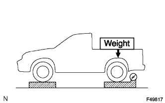
Set the vehicle to its curb weight.
-
Place weights (as necessary) on the rear deck until the rear axle load is as shown below.
Standard rear axle load Vehicle Type Specified Condition 2WD Single Cab 7845 N (800 kgf, 1764 lbf) 2WD Extra Cab 8336 N (850 kgf, 1874 lbf) 2WD Double Cab 8826 N (900 kgf, 1984 lbf) 4WD and Pre-Runner 9807 N (1000 kgf, 2205 lbf) Note
-
Be sure that the vehicle is on a level surface before starting the procedure.
-
When placing the weights on the vehicle, first place the weights so that the total is approximately 60 kg (132 lb) more than the specification. Then remove weights as necessary to adjust the load.
-
-
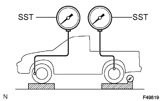
Install SST and bleed air from the brake system.
- SST
- 09709-29018
-
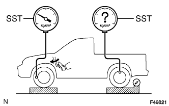
Raise the front brake fluid pressure to 10000 kPa (107.6 kgf/cm2, 1450 psi) by depressing the brake pedal, and measure the rear brake fluid pressure.
Standard rear brake fluid pressure Vehicle Type Specified Condition 2WD 5260 +/-490 kPa (53.6 +/-5.0 kgf/cm2, 762 +/-71 psi)
4WD and Pre-Runner 4450 +/-490 kPa (45.4 +/-5.0 kgf/cm2, 645 +/-71 psi)
Tech Tips
-
The pedal should not be depressed twice or released while raising the front brake fluid pressure.
-
Read the value of the rear brake fluid pressure after raising and holding the front fluid pressure for 2 seconds.
If necessary, adjust the load sensing proportioning valve.
-
-
-
ADJUST LOAD SENSING PROPORTIONING VALVE ASSEMBLY
-
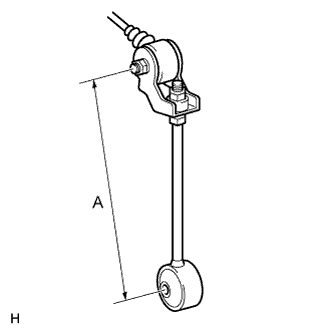
Adjust the length of the No. 2 load sensing spring shackle.
When the rear brake fluid pressure is below the standard pressure, lengthen length A.
When the rear brake fluid pressure is higher than the standard pressure, shorten length A.
Standard Initial Length (A) Vehicle Type Specified Condition 2WD 120 mm (4.764 in.) 4WD and Pre-Runner 190 mm (7.543 in.) Standard Length (A) after Adjustment Vehicle Type Specified Condition 2WD 114 to 126 mm (4.526 to 5.002 in.) 4WD and Pre-Runner 184 to 196 mm (7.305 to 7.781 in.) Tech Tips
The rear brake fluid pressure changes according to the table below by adjusting length A.
Standard Pressure Change Vehicle Type Specified Condition 2WD Changes by 140 kPa (1.4 kgf/cm2, 20.5 psi) for every 1 mm (0.0394 in.) change in length A
4WD and Pre-Runner Changes by 120 kPa (1.2 kgf/cm2, 17.6 psi) for every 1 mm (0.0394 in.) change in length A
-
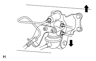
If the pressure cannot be adjusted by the No. 2 load sensing spring shackle, loosen the nuts and raise or lower the valve body.
When the pressure is below the standard pressure, lower the load sensing valve assembly.
When the pressure is higher than the standard pressure, raise the load sensing valve assembly.
-
Tighten the nuts.
- Torque:
- 13 N*m { 127 kgf*cm, 9 ft.*lbf }
-
Adjust the length of the No. 2 load sensing spring shackle again.
Tech Tips
If the length cannot be adjusted, check the load sensing valve assembly.
-