SFI SYSTEM, Diagnostic DTC:P023511
| DTC Code | DTC Name |
|---|---|
| P023511 | Turbocharger/Supercharger Boost Sensor "A" Circuit Short to Ground |
DESCRIPTION
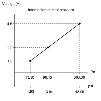
The internal sensor in the No. 1 turbo pressure sensor detects the intercooler internal pressure as a voltage.
| DTC No. | Detection Item | DTC Detection Condition | Trouble Area | MIL | Memory | Note |
|---|---|---|---|---|---|---|
| P023511 | Turbocharger/Supercharger Boost Sensor "A" Circuit Short to Ground | The No. 1 turbo pressure sensor output voltage is less than 0.97 V for 3 seconds or more (1 trip detection logic). |
|
Comes on | DTC stored | SAE Code: P0237 |
Tech Tips
When this DTC is output, check the No. 1 turbo pressure sensor in the Data List. Enter the following menus: Powertrain / Engine / Data List / All Data / Boost Pressure Sensor.
| DTC No. | Boost Pressure Sensor | Malfunction |
|---|---|---|
| P023511 | Approximately 11 kPa [2 psi] or less |
|
If the Data List values is normal it may be due to a temporary recovery from the malfunction condition. Check for intermittent problems.
MONITOR DESCRIPTION
The ECM monitors the No. 1 turbo pressure sensor voltage and uses this value to calculate the intercooler internal pressure. When the No. 1 turbo pressure sensor output voltage deviates from the normal operating range, the ECM interprets this as a malfunction in the No. 1 turbo pressure sensor circuit and stores this DTC.
Example:
If the No. 1 turbo pressure sensor output voltage is less than 0.97 V for 3 seconds or more, the ECM store this DTC
MONITOR STRATEGY
| Required Sensors/Components | No. 1 turbo pressure sensor |
| Frequency of Operation | Continuous |
CONFIRMATION DRIVING PATTERN
-
Connect the GTS to the DLC3.
-
Turn the ignition switch to ON.
-
Turn the GTS on.
-
Clear the DTCs (even if no DTCs are stored, perform the clear DTC procedure).
-
Turn the ignition switch off and wait for at least 30 seconds.
-
Turn the ignition switch to ON.
-
Turn the GTS on.
-
Start the engine and wait 5 seconds or more.
-
Enter the following menus: Powertrain / Engine / Trouble Codes.
-
Read the pending DTCs.
Tech Tips
-
If a pending DTC is output, the system is malfunctioning.
-
If a pending DTC is not output, perform the following procedure.
-
-
Enter the following menus: Powertrain / Engine / Utility / All Readiness.
-
Input the DTC: P023511.
-
Check the DTC judgment result.
GTS Display Description NORMAL
-
DTC judgment completed
-
System normal
ABNORMAL
-
DTC judgment completed
-
System abnormal
INCOMPLETE
-
DTC judgment not completed
-
Perform driving pattern after confirming DTC enabling conditions
N/A
-
Unable to perform DTC judgment
-
Number of DTCs which do not fulfill DTC preconditions has reached ECU memory limit
Tech Tips
-
If the judgment result shows NORMAL, the system is normal.
-
If the judgment result shows ABNORMAL, the system has a malfunction.
-
If the judgment result shows INCOMPLETE or N/A, perform the Confirmation Driving Pattern and check the DTC judgment result again.
-
WIRING DIAGRAM
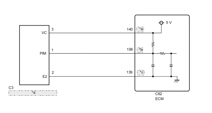
| *a | VPTA |
| *b | PTA |
| *c | EPTA |
| *d | No. 1 Turbo Pressure Sensor |
CAUTION / NOTICE / HINT
Tech Tips
Read freeze frame data using the GTS. The ECM records vehicle and driving condition information as freeze frame data the moment a DTC is stored. When troubleshooting, freeze frame data can help determine if the vehicle was moving or stationary, if the engine was warmed up or not, if the air fuel ratio was lean or rich, and other data from the time the malfunction occurred.
PROCEDURE
-
CHECK TERMINAL VOLTAGE (POWER SOURCE OF NO. 1 TURBO PRESSURE SENSOR)
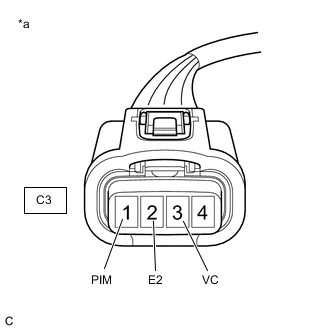
*a Front view of wire harness connector
(to No. 1 Turbo Pressure Sensor)
-
Disconnect the No. 1 turbo pressure sensor connector.
-
Turn the ignition switch to ON.
-
Measure the voltage according to the value(s) in the table below.
Standard Voltage Tester Connection Switch Condition Specified Condition C3-3 (VC) - C3-2 (E2) Ignition switch ON 4.75 to 5.25 V C3-1 (PIM) - C3-2 (E2) Ignition switch ON 3.0 to 5.25 V Result Proceed to OK NG
NG 
CHECK HARNESS AND CONNECTOR (NO. 1 TURBO PRESSURE SENSOR - ECM) Click here
OK 
-
-
REPLACE NO. 1 TURBO PRESSURE SENSOR
-
Replace the No. 1 turbo pressure sensor.
Result Proceed to NEXT
NEXT
-
-
CHECK WHETHER DTC OUTPUT RECURS (P023511)
-
Connect the GTS to the DLC3.
-
Turn the ignition switch to ON.
-
Turn the GTS on.
-
Clear the DTC.
Powertrain > Engine > Clear DTCs -
Turn the ignition switch off and wait for at least 30 seconds.
-
Turn the ignition switch to ON.
-
Turn the GTS on.
-
Drive the vehicle in accordance with the driving pattern described in the Confirmation Driving Pattern.
-
Enter the following menus: Powertrain / Engine / Trouble Codes.
Powertrain > Engine > Trouble Codes -
Read the DTCs.
Result Result Proceed to DTCs are not output A DTC P023511 is output B
A 
CHECK FOR INTERMITTENT PROBLEMS Click here
B
REPLACE ECM Click here
-
-
CHECK HARNESS AND CONNECTOR (NO. 1 TURBO PRESSURE SENSOR - ECM)
-
Disconnect the C3 No. 1 turbo pressure sensor connector.
-
Disconnect the C62 ECM connector.
-
Measure the resistance according to the value(s) in the table below.
Standard Resistance Tester Connection Condition Specified Condition C3-3 (VC) - C62-140 (VPTA) Always Below 1 Ω C3-1 (PIM) or C62-108 (PTA) - Body ground and other terminals Always 10 kΩ or higher Result Proceed to OK NG
OK
REPLACE ECM Click here
NG
REPAIR OR REPLACE HARNESS OR CONNECTOR
-