FRONT SUSPENSION MEMBER REMOVAL
CAUTION / NOTICE / HINT
The necessary procedures (adjustment, calibration, initialization, or registration) that must be performed after parts are removed and installed, or replaced during front suspension crossmember sub-assembly removal/installation are shown below.
| Replaced Part or Performed Procedure | Necessary Procedure | Effect/Inoperative Function when Necessary Procedure not Performed | Link |
|---|---|---|---|
| Front wheel alignment adjustment |
|
|
|
| Suspension, tires, etc. (The vehicle height changes because of suspension or tire replacement) |
Initialize No. 1 headlight ECU sub-assembly LH | Automatic headlight beam level control system |
PROCEDURE
-
ALIGN FRONT WHEELS FACING STRAIGHT AHEAD
-
SECURE STEERING WHEEL
-
REMOVE COLUMN HOLE COVER SILENCER SHEET
-
SEPARATE NO. 2 STEERING INTERMEDIATE SHAFT ASSEMBLY
-
SEPARATE NO. 1 STEERING COLUMN HOLE COVER SUB-ASSEMBLY
-
REMOVE FRONT WHEELS
-
REMOVE NO. 1 ENGINE UNDER COVER
-
REMOVE REAR ENGINE UNDER COVER LH
-
REMOVE REAR ENGINE UNDER COVER RH
-
REMOVE FRONT FLOOR COVER LH (w/ Cover)
-
REMOVE FRONT FLOOR COVER RH (w/ Cover)
Tech Tips
Use the same procedure as for the LH side.
-
REMOVE REAR SIDE RAIL REINFORCEMENT SUB-ASSEMBLY LH
-
Remove the 4 bolts and rear side rail reinforcement sub-assembly LH from the front suspension crossmember sub-assembly and vehicle body.
-
-
REMOVE REAR SIDE RAIL REINFORCEMENT SUB-ASSEMBLY RH
Tech Tips
Perform the same procedure as for the LH side.
-
SEPARATE FRONT STABILIZER LINK ASSEMBLY LH
-
Remove the nut and front stabilizer link assembly LH from the front shock absorber assembly.
Note
Do not damage the boot of the ball joint.
Tech Tips
If the ball joint turns together with the nut, use a 6 mm hexagon socket wrench to hold the stud bolt.
-
-
SEPARATE FRONT STABILIZER LINK ASSEMBLY RH
Tech Tips
Perform the same procedure as for the LH side.
-
SEPARATE TIE ROD END SUB-ASSEMBLY LH
-
SEPARATE TIE ROD END SUB-ASSEMBLY RH
Tech Tips
Perform the same procedure as for the LH side.
-
SEPARATE FRONT LOWER NO. 1 SUSPENSION ARM SUB-ASSEMBLY LH
-
Remove the bolt and 2 nuts and separate the front lower No. 1 suspension arm sub-assembly from the front lower ball joint assembly.
-
-
SEPARATE FRONT LOWER NO. 1 SUSPENSION ARM SUB-ASSEMBLY RH
Tech Tips
Perform the same procedure as for the LH side.
-
REMOVE FRONT SUSPENSION CROSSMEMBER SUB-ASSEMBLY
-
for AWD:
-
Remove the bolt and separate the wire harness clamp bracket from the front suspension crossmember sub-assembly.
-
-
for 2WD:
-
Remove the 2 bolts and separate the 2 wire harness clamp brackets from the front suspension crossmember sub-assembly.
-
-
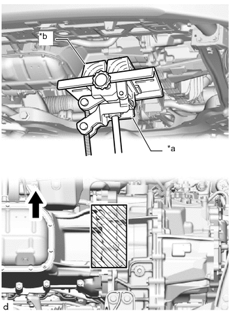
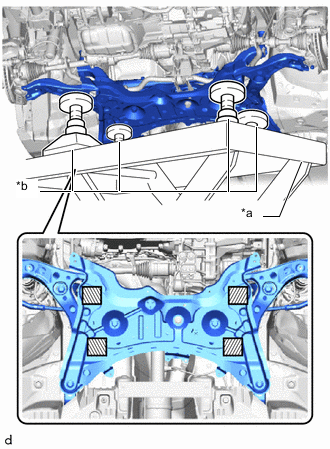
*a Transmission Jack *b Wooden Block 
Front of the Vehicle 
Wooden block placement location Using a transmission jack and a wooden block, support the engine assembly with transaxle.
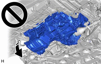
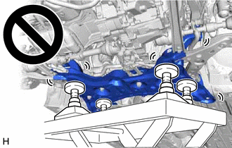
CAUTION:
-
Support the engine assembly with transaxle until the front suspension crossmember sub-assembly is installed.
-
If the support is removed before the front suspension crossmember sub-assembly is installed, the engine assembly with transaxle may drop.
-
-
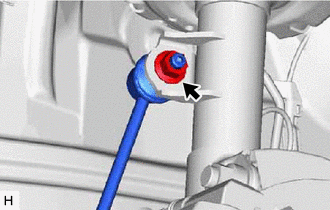
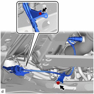
Remove the bolt and separate the engine moving control rod.
-
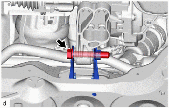
*a Engine Lifter *b Attachment Attachment placement location Support the front suspension crossmember sub-assembly with an engine lifter using 4 attachments or equivalent tools as shown in the illustration.
CAUTION:
-
The front suspension crossmember sub-assembly is a very heavy component. Make sure that it is supported securely.
-
If the front suspension crossmember sub-assembly is not securely supported, it may drop, resulting in serious injury.
Note
Use attachments to keep the front suspension crossmember sub-assembly level.
-
-
Remove the 6 bolts and front suspension crossmember sub-assembly.
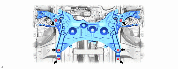
-
Slowly lower the front suspension crossmember sub-assembly.
Note
When lowering the front suspension crossmember sub-assembly, be careful not to damage the vehicle body or other components installed to the vehicle.
-
-
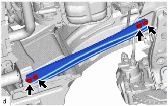
REMOVE STEERING LINK ASSEMBLY
-
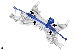
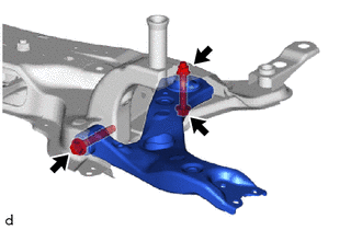
Remove the 2 bolts, 2 nuts and steering link assembly from the front suspension crossmember sub-assembly.
Note
Because the nut has its own stopper, do not turn the nut. Loosen the bolt with the nut secured.
-
-
REMOVE FRONT NO. 1 STABILIZER BRACKET LH
-
REMOVE FRONT NO. 1 STABILIZER BRACKET RH
Tech Tips
Perform the same procedure as for the LH side.
-
REMOVE FRONT STABILIZER BAR
-
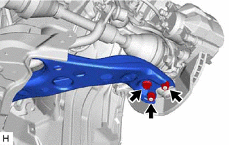
REMOVE FRONT LOWER NO. 1 SUSPENSION ARM SUB-ASSEMBLY LH
-
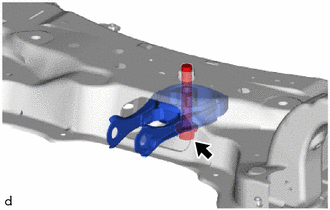
Remove the 2 bolts, nut and front lower No. 1 suspension arm sub-assembly LH from the front suspension crossmember sub-assembly.
Note
Because the nut has its own stopper, do not turn the nut. Loosen the bolt with the nut secured.
-
-
REMOVE FRONT LOWER NO. 1 SUSPENSION ARM SUB-ASSEMBLY RH
Tech Tips
Perform the same procedure as for the LH side.
-
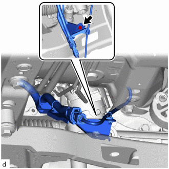
REMOVE ENGINE MOVING CONTROL ROD
-
Remove the bolt and engine moving control rod from the front suspension crossmember sub-assembly.
-
-
REMOVE FRONT SUSPENSION MEMBER PLATE
-
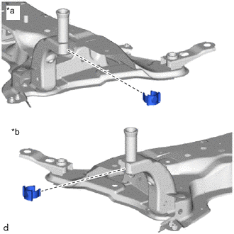
*a for LH Side *b for RH Side Remove the 2 front suspension member plates from the front suspension crossmember sub-assembly.
-
-
REMOVE HOLE PLUG
-
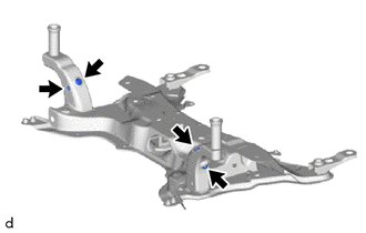
Remove the 4 hole plugs from the front suspension crossmember sub-assembly.
Tech Tips
There are 2 different shapes of hole plug.
-