FUEL PRESSURE SENSOR(for High Pressure) INSTALLATION
CAUTION / NOTICE / HINT
Note
This procedure includes the installation of small-head bolts. Refer to Small-Head Bolts of Basic Repair Hint to identify the small-head bolts.
PROCEDURE
-
INSTALL FUEL PRESSURE SENSOR
Tech Tips
Perform "Inspection After Repair" after replacing the fuel pressure sensor.
-
w/ Canistaer Pump Module:
-
w/o Canistaer Pump Module:
-
Set a new fuel pressure sensor to the No. 2 fuel delivery pipe sub-assembly RH.
Note
-
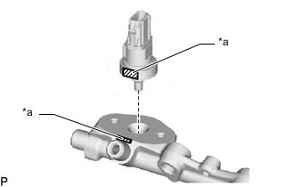
*a Flat Surface Align the flat surface on the fuel pressure sensor with the flat surface on the No. 2 fuel delivery pipe sub-assembly RH.
-
Do not allow dust or dirt to enter the sensor.
-
If a fuel pressure sensor is dropped or struck, replace it with a new one.
-
-
Set the No. 1 fuel pressure sensor holder to the No. 2 fuel delivery pipe sub-assembly RH.
Note
-
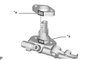
*a Flat Surface Align the flat surface on the No. 1 fuel pressure sensor holder with the flat surface on the fuel pressure sensor.
-
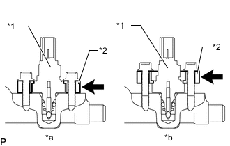
*1 Fuel Pressure Sensor *2 No. 1 Fuel Pressure Sensor Holder *a CORRECT *b INCORRECT Make sure to install the No. 1 fuel pressure sensor holder in the correct direction.
-
-
Install the 2 bolts.
- Torque:
- 10 N*m { 102 kgf*cm, 7 ft.*lbf }
-
Connect the connector to the fuel pressure sensor.
-
-
INSTALL INTAKE MANIFOLD
-
INSTALL FUEL HOSE PROTECTOR
-
INSTALL FUEL TUBE SUB-ASSEMBLY
-
INSTALL FUEL TUBE SUB-ASSEMBLY
-
CONNECT FUEL TUBE SUB-ASSEMBLY
-
INSTALL INTAKE AIR SURGE TANK ASSEMBLY WITH INTERCOOLER
-
INSTALL COWL TOP VENTILATOR LOUVER SUB-ASSEMBLY
-
CONNECT CABLE TO NEGATIVE BATTERY TERMINAL
Note
When disconnecting the cable, some systems need to be initialized after the cable is reconnected.
-
INSPECT FOR FUEL LEAK
-
PERFORM INITIALIZATION
-
Perform "Inspection After Repair" after replacing the fuel pressure sensor.
-
w/ Canistaer Pump Module:
-
w/o Canistaer Pump Module:
-
-