ECD SYSTEM (w/ EGR Cooler), Diagnostic DTC:P0340
| DTC Code | DTC Name |
|---|---|
| P0340 | Camshaft Position Sensor "A" Circuit (Bank 1 or Single Sensor) |
DESCRIPTION
The camshaft position sensor (G signal) consists of a magnet, iron core and pickup coil.
The G signal plate has 5 teeth on its outer circumference and is installed on the pump drive shaft pulley. When the pump drive shaft pulley rotate, the protrusion on the signal plate and the air gap on the pickup coil change, causing fluctuations in the magnetic field and generating an electromotive force in the pickup coil.
The NE signal plate has 34 teeth and is mounted on the No. 1 crankshaft position sensor plate. The NE signal sensor generates 34 signals for every engine revolution. The ECM detects the standard crankshaft angle based on the G signal and the actual crankshaft angle and the engine speed by the NE signal.
| DTC No. | DTC Detection Condition | Trouble Area |
|---|---|---|
| P0340 |
|
|
Reference: Inspection using the oscilloscope.
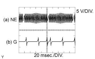
While idling, the correct waveform is shown in the diagram.
Tech Tips
G stands for the camshaft position sensor signal, and NE stands for the crankshaft position sensor signal.
| Item | Content |
|---|---|
| Terminal | (b) G+ - G- |
| Tester Range | 5 V/DIV., 20 msec./DIV. |
| Condition | Cranking or idling |
WIRING DIAGRAM
Refer to DTC P0335 Click here.
INSPECTION PROCEDURE
Note
After replacing the ECM, the new ECM needs registration Click here and initialization Click here.
Tech Tips
Read freeze frame data using the intelligent tester. Freeze frame data records the engine condition when malfunctions are detected. When troubleshooting, freeze frame data can help determine if the vehicle was moving or stationary, if the engine was warmed up or not, and other data from the time the malfunction occurred.
PROCEDURE
-
INSPECT CAMSHAFT POSITION SENSOR
-
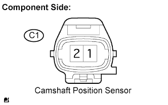
Disconnect the C1 camshaft position sensor connector.
-
Measure the resistance of the camshaft position sensor.
Standard resistance Tester Connection Specified Condition 1 - 2 835 to 1,400 Ω at cold 1 - 2 1,060 to 1,645 Ω at hot Tech Tips
In the table above, the terms "Cold" and "Hot" refer to the temperature of the coils in the sensors. "Cold" means approximately -10 to 50°C (14 to 122°F). "Hot" means approximately 50 to 100°C (122 to 212°F).
NG 
REPLACE CAMSHAFT POSITION SENSOR
OK 
-
-
CHECK HARNESS AND CONNECTOR (CAMSHAFT POSITION SENSOR - ECM)
-
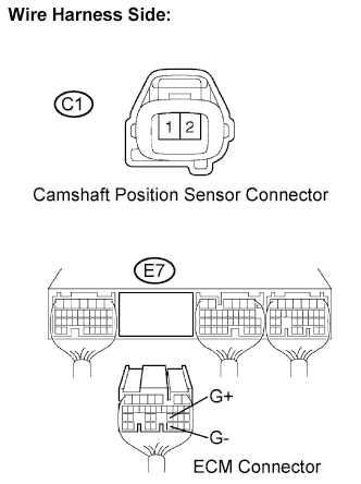
Disconnect the C1 camshaft position sensor connector.
-
Disconnect the E7 ECM connector.
-
Measure the resistance of the wire harness side connectors.
Standard resistance (Check for open) Tester Connection Specified Condition C1-1 - G+ (E7-23) Below 1 Ω C1-2 - G- (E7-31) Below 1 Ω Standard resistance (Check for short) Tester Connection Specified Condition C1-1 or G+ (E7-23) - Body ground 10 kΩ or higher C1-2 or G- (E7-31) - Body ground 10 kΩ or higher
NG
REPAIR OR REPLACE HARNESS OR CONNECTOR
OK
-
-
CHECK CAMSHAFT POSITION SENSOR (SENSOR INSTALLATION)
-
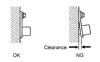
Check the sensor installation.
OK Sensor is installed correctly.
NG
TIGHTEN SENSOR
OK
-
-
CHECK PUMP DRIVE SHAFT PULLEY
-
Check the condition of the pump drive shaft pulley.
OK Timing sprocket does not have any cracks or deformation.
NG
REPLACE PUMP DRIVE SHAFT PULLEY
OK 
REPLACE ECM Click here
-