PARK / NEUTRAL POSITION SWITCH REMOVAL
CAUTION / NOTICE / HINT
The necessary procedures (adjustment, calibration, initialization or registration) that must be performed after parts are removed and installed, or replaced during park/neutral position switch assembly removal/installation are shown below.
| Replaced Part or Performed Procedure | Necessary Procedure | Effect/Inoperative Function when Necessary Procedure not Performed | Link |
|---|---|---|---|
| Battery terminal is disconnected/reconnected | Memorize steering angle neutral point | LKA/LDA System | |
| Pre-crash safety system | |||
| Lighting system (EXT)
|
|||
| Adaptive high beam system | |||
| Drive the vehicle until stop and start control is permitted (approximately 15 to 60 minutes) | Stop and start system | ||
| Memorize steering angle neutral point | Parking Assist Monitor System (w/ Parallel Parking Assist Function) | ||
| Parking Assist Monitor System (w/o Parallel Parking Assist Function) | |||
| Panoramic view monitor system | |||
| Initialize back door lock | Power door lock control system | ||
| Reset back door close position | Power back door system |
PROCEDURE
-
PRECAUTION
Note
After turning the engine switch off, waiting time may be required before disconnecting the cable from the negative (-) battery terminal. Therefore, make sure to read the disconnecting the cable from the negative (-) battery terminal notices before proceeding with work.
-
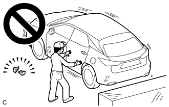
SECURE VEHICLE
-
Fully apply the parking brake and chock a wheel.
CAUTION:
-
Make sure to apply the parking brake and chock a wheel before performing this procedure.
-
If the vehicle is not secure and the shift lever is moved to N, the vehicle may suddenly move, possibly resulting in an accident or serious injury.
-
-
-
REMOVE COOL AIR INTAKE DUCT SEAL
-
REMOVE INLET AIR CLEANER ASSEMBLY
-
DISCONNECT CABLE FROM NEGATIVE BATTERY TERMINAL
Note
When disconnecting the cable, some systems need to be initialized after the cable is reconnected.
-
REMOVE BATTERY
-
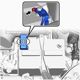
Disengage the 2 claws to open the battery terminal cap.
-
Loosen the nut and disconnect the cable from the positive (+) battery terminal.
-
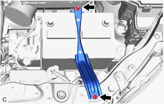
Remove the bolt, nut and battery clamp sub-assembly.
-
Remove the battery and battery tray.
-
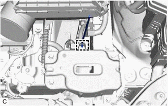
Remove the battery clamp bolt from the battery carrier sub-assembly.
-
-
DISCONNECT TRANSMISSION CONTROL CABLE ASSEMBLY
-
Move the shift lever to N.
-
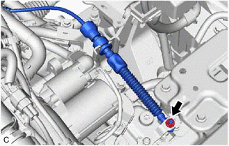
Remove the nut and disconnect the transmission control cable assembly from the transmission control shaft lever.
-
-
REMOVE PARK/NEUTRAL POSITION SWITCH ASSEMBLY
-
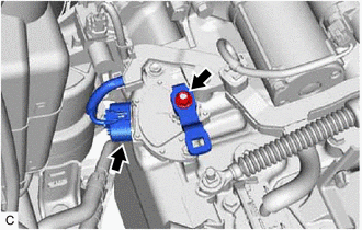
Disconnect the park/neutral position switch assembly connector.
-
Remove the nut and transmission control shaft lever from the manual valve lever shaft sub-assembly.
-
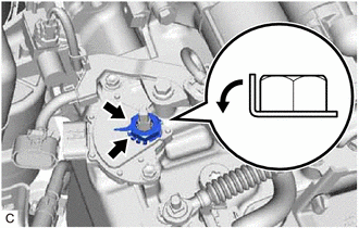
Using a screwdriver, bend back the tabs of the lock plate and remove the lock nut and lock plate from the park/neutral position switch assembly.
-
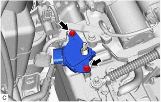
Remove the 2 bolts and park/neutral position switch assembly from the automatic transaxle case sub-assembly.
Note
Before removing the park/neutral position switch assembly, remove any dirt or rust on the installation portion of the manual valve lever shaft sub-assembly. Be sure to remove the park/neutral position switch assembly straight along the manual valve lever shaft sub-assembly while being careful not to deform the plate spring that supports the manual valve lever shaft sub-assembly. If the plate spring is deformed, the park/neutral position switch assembly cannot be reinstalled correctly.
-