CAN COMMUNICATION SYSTEM (w/ VSC) Check CAN Bus Lines for Short Circuit
DESCRIPTION
There may be a short circuit between the CAN bus lines when the resistance between terminals 6 (CANH) and 14 (CANL) of the DLC3 is below 54 Ω.
| Symptom | Trouble Area |
|---|---|
| Resistance between terminals 6 (CANH) and 14 (CANL) of the DLC3 is below 54 Ω. |
|
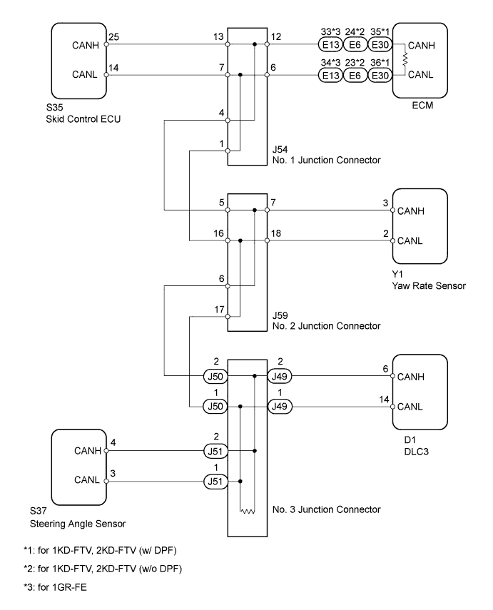
WIRING DIAGRAM
INSPECTION PROCEDURE
Tech Tips
Operating the ignition switch, any switches or any doors triggers related ECU and sensor communication with the CAN, which causes resistance variation.
PROCEDURE
-
DISCONNECT CABLE FROM NEGATIVE BATTERY TERMINAL
-
Disconnect the cable from the negative (-) battery terminal before measuring the resistances of the main wire and the branch wire.
CAUTION:
Wait at least 90 seconds after disconnecting the cable from the negative (-) battery terminal to disable the SRS system.
Note
When disconnecting the cable from the negative (-) battery terminal, some systems need to be initialized after the cable is reconnected Click here.
NEXT 
-
-
CHECK FOR SHORT IN CAN BUS WIRES (DLC3 BRANCH WIRE)
-
Disconnect the J49 No. 3 junction connector.
-
Measure the resistance according to the value(s) in the table below.
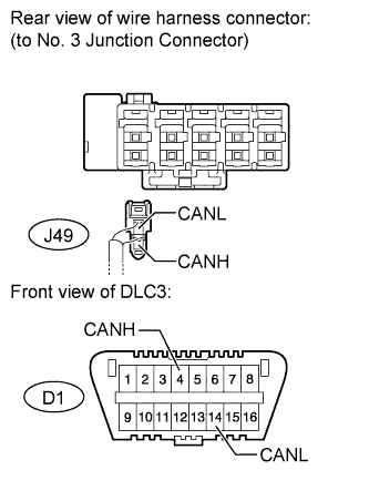
Standard Resistance Tester Connection Switch Condition Specified Condition J49-2 (CANH) - D1-6 (CANH) Ignition switch off Below 1 Ω J49-1 (CANL) - D1-14 (CANL) Ignition switch off Below 1 Ω
NG 
REPAIR OR REPLACE CAN BRANCH WIRE CONNECTED TO DLC3 (CANH, CANL)
OK
-
-
CONNECT CONNECTOR
-
Reconnect the J49 No. 3 junction connector.
NEXT
-
-
CHECK FOR SHORT IN CAN BUS WIRES (NO. 1 JUNCTION CONNECTOR SIDE)
-
Disconnect the J54 No. 1 junction connector.
-
Measure the resistance according to the value(s) in the table below.
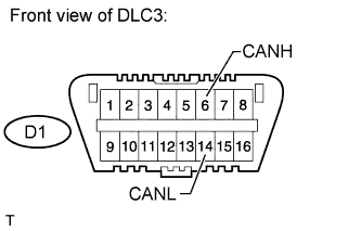
Standard Resistance Tester Connection Switch Condition Specified Condition D1-6 (CANH) - D1-14 (CANL) Ignition switch off 108 to 132 Ω
NG 
CONNECT CONNECTOR Click here
OK
-
-
CHECK FOR SHORT IN CAN BUS WIRES (NO. 1 JUNCTION CONNECTOR - SKID CONTROL ECU)
-

Measure the resistance according to the value(s) in the table below.
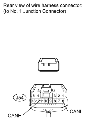
Standard Resistance Tester Connection Switch Condition Specified Condition J54-13 (CANH) - J54-7 (CANL) Ignition switch off 200 Ω or higher
NG
CONNECT CONNECTOR Click here
OK
-
-
CHECK FOR SHORT IN CAN BUS WIRES (NO. 1 JUNCTION CONNECTOR - ECM)
-
Measure the resistance according to the value(s) in the table below.
Standard Resistance Tester Connection Switch Condition Specified Condition J54-12 (CANH) - J54-6 (CANL) Ignition switch off 108 to 132 Ω
NG
CONNECT CONNECTOR Click here
OK 
REPLACE NO. 1 JUNCTION CONNECTOR
-
-
CONNECT CONNECTOR
-
Reconnect the J54 No. 1 junction connector.
NEXT
-
-
CHECK FOR SHORT IN CAN BUS WIRES (SKID CONTROL ECU)
-
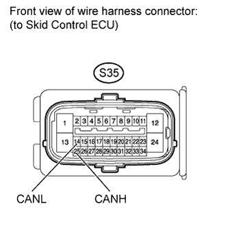
Disconnect the S35 skid control ECU connector.
-
Measure the resistance according to the value(s) in the table below.
Standard Resistance Tester Connection Switch Condition Specified Condition S35-25 (CANH) - S35-14 (CANL) Ignition switch off 54 to 69 Ω Result Result Proceed to OK (for LHD) A OK (for RHD) B NG C
B
REPLACE BRAKE ACTUATOR ASSEMBLY (SKID CONTROL ECU) Click here
C
REPAIR OR REPLACE CAN BRANCH WIRE CONNECTED TO SKID CONTROL ECU (CANH, CANL)
A
REPLACE BRAKE ACTUATOR ASSEMBLY (SKID CONTROL ECU) Click here
-
-
CONNECT CONNECTOR
-
Reconnect the J54 No. 1 junction connector.
NEXT
-
-
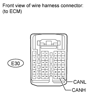
CHECK FOR SHORT IN CAN BUS WIRES (ECM)
-
for 1KD-FTV, 2KD-FTV (w/ DPF):
-
Disconnect the E30 ECM connector.
-
Measure the resistance according to the value(s) in the table below.
Standard Resistance Tester Connection Switch Condition Specified Condition E30-35 (CANH) - E30-36 (CANL) Ignition switch off 108 to 132 Ω
-
-
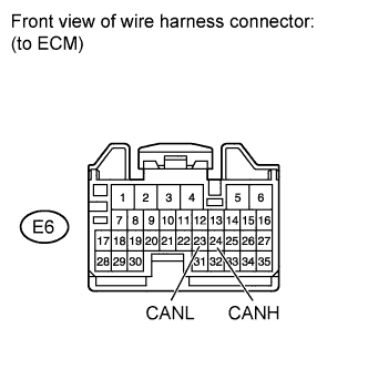
for 1KD-FTV, 2KD-FTV (w/o DPF):
-
Disconnect the E6 ECM connector.
-
Measure the resistance according to the value(s) in the table below.
Standard Resistance Tester Connection Switch Condition Specified Condition E6-24 (CANH) - E6-23 (CANL) Ignition switch off 108 to 132 Ω
-
-
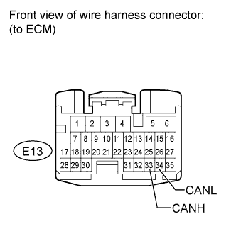
for 1GR-FE:
-
Disconnect the E13 ECM connector.
-
Measure the resistance according to the value(s) in the table below.
Standard Resistance Tester Connection Switch Condition Specified Condition E13-33 (CANH) - E13-34 (CANL) Ignition switch off 108 to 132 Ω
Result Result Proceed to OK (for 1KD-FTV) A OK (for 2KD-FTV) B OK (for 1GR-FE) C NG D -
B
REPLACE ECM Click here
C
REPLACE ECM Click here
D
REPAIR OR REPLACE CAN MAIN WIRE CONNECTED TO ECM (CANH, CANL)
A
REPLACE ECM Click here
-
-
CONNECT CONNECTOR
-
Reconnect the J54 No. 1 junction connector.
NEXT
-
-
CHECK FOR SHORT IN CAN BUS WIRES (NO. 2 JUNCTION CONNECTOR - NO. 1 JUNCTION CONNECTOR)
-
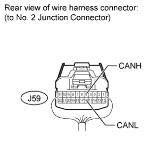
Disconnect the J59 No. 2 junction connector.
-
Measure the resistance according to the value(s) in the table below.
Standard Resistance Tester Connection Switch Condition Specified Condition J59-5 (CANH) - J59-16 (CANL) Ignition switch off 108 to 132 Ω
NG
REPAIR OR REPLACE CAN MAIN WIRE OR CONNECTOR (NO. 2 JUNCTION CONNECTOR - NO. 1 JUNCTION CONNECTOR)
OK
-
-
CHECK FOR SHORT IN CAN BUS WIRES (NO. 2 JUNCTION CONNECTOR SIDE)
-
Measure the resistance according to the value(s) in the table below.
Standard Resistance Tester Connection Switch Condition Specified Condition D1-6 (CANH) - D1-14 (CANL) Ignition switch off 108 to 132 Ω
NG
CONNECT CONNECTOR Click here
OK
-
-
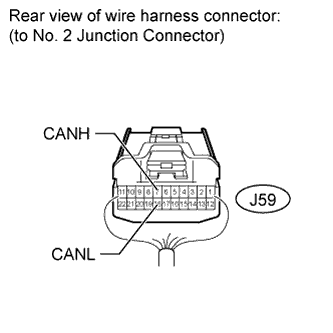
CHECK FOR SHORT IN CAN BUS WIRES (NO. 2 JUNCTION CONNECTOR - YAW RATE SENSOR)
-
Measure the resistance according to the value(s) in the table below.
Standard Resistance Tester Connection Switch Condition Specified Condition J59-7 (CANH) - J59-18 (CANL) Ignition switch off 200 Ω or higher
NG
CONNECT CONNECTOR Click here
OK
REPLACE NO. 2 JUNCTION CONNECTOR
-
-
CONNECT CONNECTOR
-
Reconnect the J59 No. 2 junction connector.
NEXT
-
-
CHECK FOR SHORT IN CAN BUS WIRES (YAW RATE SENSOR)
-
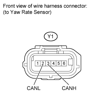
Disconnect the Y1 yaw rate sensor connector.
-
Measure the resistance according to the value(s) in the table below.
Standard Resistance Tester Connection Switch Condition Specified Condition Y1-3 (CANH) - Y1-2 (CANL) Ignition switch off 54 to 69 Ω
NG
REPAIR OR REPLACE CAN BRANCH WIRE CONNECTED TO YAW RATE SENSOR (CANH, CANL)
OK
REPLACE YAW RATE SENSOR Click here
-
-
CONNECT CONNECTOR
-
Reconnect the J59 No. 2 junction connector.
NEXT
-
-
CHECK FOR SHORT IN CAN BUS WIRES (NO. 3 JUNCTION CONNECTOR - NO. 2 JUNCTION CONNECTOR)
-
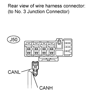
Disconnect the J50 No. 3 junction connector.
-
Measure the resistance according to the value(s) in the table below.
Standard Resistance Tester Connection Switch Condition Specified Condition J50-2 (CANH) - J50-1 (CANL) Ignition switch off 108 to 132 Ω
NG
REPAIR OR REPLACE CAN MAIN WIRE OR CONNECTOR (NO. 3 JUNCTION CONNECTOR - NO. 2 JUNCTION CONNECTOR)
OK
-
-
CHECK FOR SHORT IN CAN BUS WIRES (NO. 3 JUNCTION CONNECTOR - STEERING ANGLE SENSOR)
-
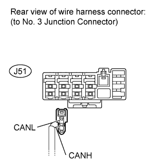
Disconnect the J51 No. 3 junction connector.
-
Measure the resistance according to the value(s) in the table below.
Standard Resistance Tester Connection Switch Condition Specified Condition J51-2 (CANH) - J51-1 (CANL) Ignition switch off 200 Ω or higher
NG
CONNECT CONNECTOR Click here
OK
REPLACE NO. 3 JUNCTION CONNECTOR
-
-
CONNECT CONNECTOR
-
Reconnect the J50 and J51 No. 3 junction connectors.
NEXT
-
-
CHECK FOR SHORT IN CAN BUS WIRES (STEERING ANGLE SENSOR)
-
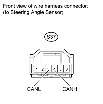
Disconnect the S37 steering angle sensor connector.
-
Measure the resistance according to the value(s) in the table below.
Standard Resistance Tester Connection Switch Condition Specified Condition S37-4 (CANH) - S37-3 (CANL) Ignition switch off 54 to 69 Ω
NG
REPAIR OR REPLACE CAN BRANCH WIRE CONNECTED TO STEERING ANGLE SENSOR (CANH, CANL)
OK
REPLACE SPIRAL CABLE (STEERING ANGLE SENSOR) Click here
-