ENGINE ASSEMBLY REMOVAL
Note
-
When replacing the injectors (including shuffling the injectors between the cylinders), common rail or cylinder head, it is necessary to replace the injection pipes with new ones.
-
When replacing the fuel supply pump, common rail, cylinder block, cylinder head, cylinder head gasket or timing gear case, it is necessary to replace the fuel inlet pipe with a new one.
-
DISCONNECT CABLE FROM NEGATIVE BATTERY TERMINAL
CAUTION:
Wait at least 90 seconds after disconnecting the cable from the negative (-) battery terminal to prevent airbag activation.
Note
When disconnecting the cable, some systems need to be initialized after the cable is reconnected Click here.
-
REMOVE HOOD SUB-ASSEMBLY
-
Disconnect the washer nozzle hose.
-
Remove the 4 bolts and hood.
-
-
REMOVE NO. 1 ENGINE UNDER COVER (for 4WD)
-
Remove the 4 bolts and No. 1 engine under cover.
-
-
REMOVE NO. 2 ENGINE UNDER COVER (for 4WD)
-
Remove the 2 bolts and No. 2 engine under cover.
-
-
DRAIN ENGINE OIL
-
Remove the oil filler cap.
-
Remove the oil drain plug, and drain the engine oil from the oil pan.
Note
Collect the oil in an oil disposal container.
-
-
LOOSEN FUEL TANK CAP ASSEMBLY
-
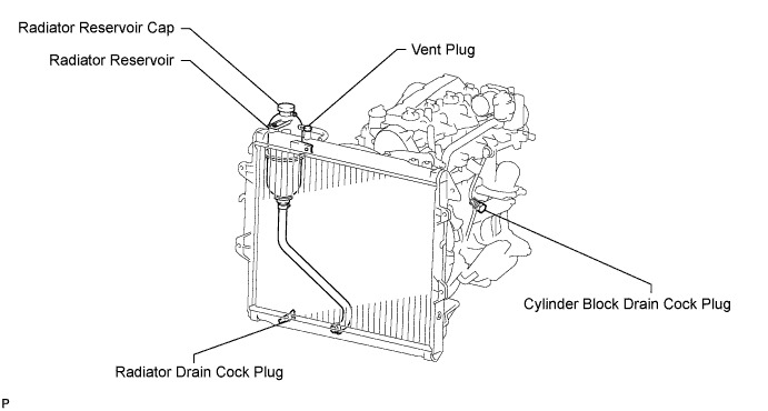
DRAIN ENGINE COOLANT
Note
Do not remove the radiator reservoir cap while the engine and radiator are still hot. Pressurized, hot engine coolant and steam may be released and cause serious burns.
-

Drain the coolant by removing the reservoir cap and, using a wrench, remove the vent plug.
-
Loosen the cylinder block drain cock plug and the radiator drain cock plug.
Tech Tips
Collect the coolant in a container and dispose of it according to the regulations in your area.
-
-
REMOVE BATTERY BRACKET
-
REMOVE BATTERY AND BATTERY TRAY
-
REMOVE AIR CLEANER ASSEMBLY
-
for Ventilation Hose Type:
Disconnect the ventilation hose.
-
w/ Mass Air Flow Meter:
Disconnect the mass air flow meter sensor connector.
-
w/ Intake Air Temperature Sensor:
Disconnect the intake air temperature sensor connector.
-
Loosen the hose clamp.
-
Remove the 2 bolts and air cleaner.
-
-
REMOVE NO. 1 ENGINE COVER SUB-ASSEMBLY (w/ EGR Cooler)
-
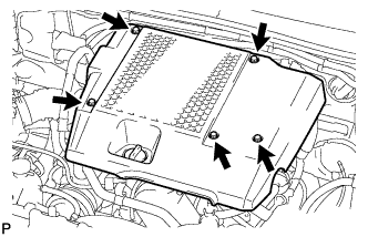
Remove the 3 bolts, 2 nut and engine cover.
-
-
REMOVE INTERCOOLER ASSEMBLY WITH INTAKE AIR CONNECTOR (w/ EGR Cooler)
-
Detach the 2 clamps.
-
Disconnect the vacuum hose from the manifold absolute pressure sensor.
-
Disconnect the IAT sensor connector and manifold absolute diesel pressure sensor connector.
-
Loosen the 2 hose clamps of the No. 1 air hose.
-
Loosen the 2 hose clamps of the No. 2 air hose.
-
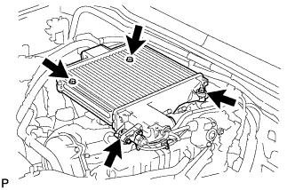
Remove the 4 bolts and intercooler.
-
-
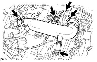
REMOVE NO. 2 AIR CLEANER PIPE SUB-ASSEMBLY (w/o EGR Cooler)
-
Disconnect the manifold absolute pressure sensor connector.
-
Disconnect the vacuum hose from the gas filter.
-
Loosen the 2 clamps.
-
Remove the bolt and disconnect the pipe together with the 2 air hoses.
-
-
REMOVE RADIATOR ASSEMBLY
-
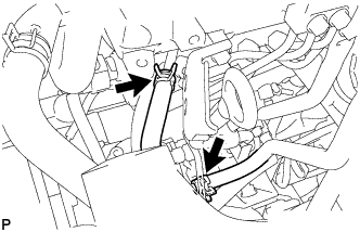
DISCONNECT HEATER HOSE
-
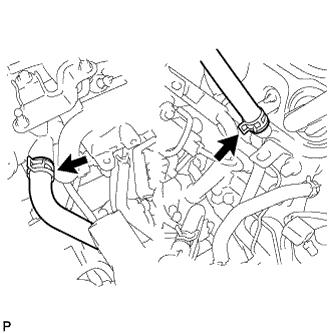
Disconnect the 2 heater hoses.
-
-
DISCONNECT PRESSURE FEED TUBE ASSEMBLY
-
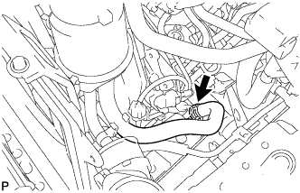
Disconnect the oil reservoir to pump hose.
-
Disconnect the pressure feed tube.
-
-
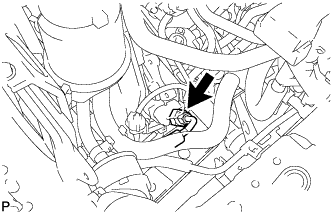
DISCONNECT FUEL HOSE
-
Disconnect the 2 fuel hoses.
-
-
DISCONNECT UNION TO CONNECTOR TUBE HOSE
-
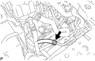
Disconnect the union to connector tube hose.
-
-
REMOVE GLOVE COMPARTMENT DOOR ASSEMBLY
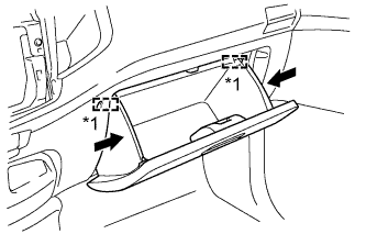
Text in Illustration *1 Stopper
-
Slightly bend the upper part of the glove compartment door to release the 2 stoppers and open the glove compartment door until it is horizontal.
-
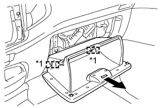
Text in Illustration *1 Hinge Pull the glove compartment door toward the rear of the vehicle to detach the 2 hinges and remove the glove compartment door.
-
-
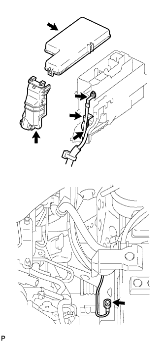
DISCONNECT WIRE HARNESS
-
Remove the upper relay block cover.
-
Remove the side relay block cover.
-
Remove the nut and disconnect the engine room junction block wire.
-
Disconnect the 2 engine room junction block connectors.
-
Remove the bolt and disconnect the ground cable.
-
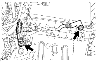
Remove the 2 nuts, detach the clamp and disconnect the wire harness.
-
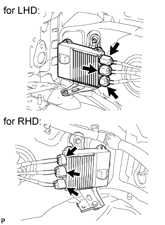
Disconnect the 3 EDU connectors.
-
w/ A.D.D.
Disconnect the 4WD control ECU connector.
-
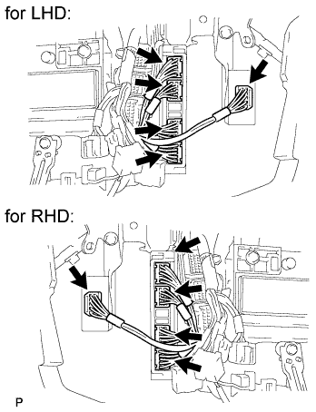
Disconnect the 4 ECM connectors.
-
-
DISCONNECT COOLER COMPRESSOR ASSEMBLY (w/ Air Conditioning System)
-
Remove the 4 bolts and disconnect the cooler compressor.
Tech Tips
It is not necessary to completely remove the compressor. With the hoses connected to the compressor, hang the compressor on the vehicle body with a rope.
-
-
REMOVE TRANSMISSION ASSEMBLY
-
for R151/R151F:
-
for G50:
-
-
REMOVE CLUTCH COVER ASSEMBLY
-
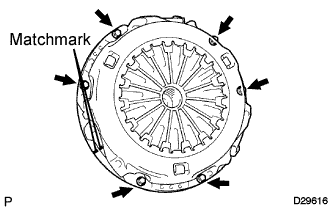
Place matchmarks on the clutch cover and flywheel.
-
Loosen each set bolt one turn at a time until spring tension is released.
-
Remove the 6 set bolts and pull off the clutch cover.
Note
Do not drop the clutch disc.
-
-
REMOVE CLUTCH DISC ASSEMBLY
Note
Keep the lining part of the clutch disc, pressure plate and surface of the flywheel away from oil and foreign matter.
-
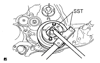
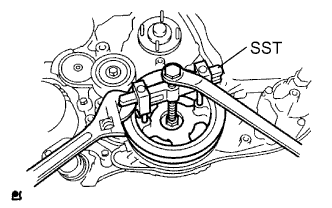
REMOVE FLYWHEEL SUB-ASSEMBLY
-
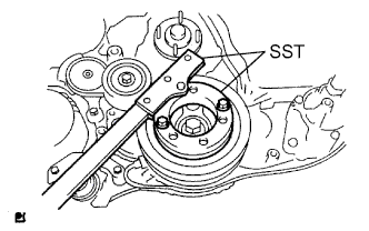
Using SST, hold the crankshaft pulley.
- SST
- 09213-58014
- 09330-00021
-
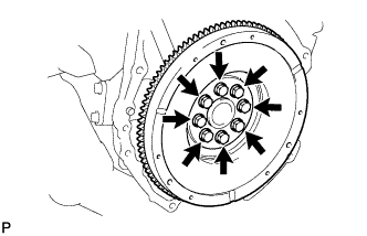
Remove the 8 bolts and flywheel.
-
-
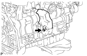
REMOVE REAR END PLATE
-
Remove the bolt and rear end plate.
-
-
REMOVE ENGINE ASSEMBLY
-
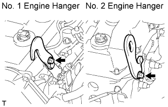
Install a No. 1 engine hanger and No. 2 engine hanger with 2 bolts as shown in the illustration.
Tech Tips
Part No.No. 1 Engine hanger w/ EGR cooler 12284-30060 Bolt (91552-81014) w/o EGR cooler 12284-30020 Bolt (91552-81014) No. 2 Engine hanger 12282-67030 Bolt (91642-81030) - Torque:
- for No. 1 engine hanger
- 25 N*m { 255 kgf*cm, 18 ft.*lbf }
- for No. 2 engine hanger
- 60 N*m { 612 kgf*cm, 44 ft.*lbf }
Note
Install the engine hangers with new bolts.
-
Attach an engine sling device and hang the engine with a chain block.
-
Remove the bolt and No. 2 cylinder block insulator.
-
Remove the 4 bolts and 4 nuts.
-
Remove the engine by operating the engine sling device and chain block.
-
-
FIX ENGINE ON ENGINE STAND
-
REMOVE ENGINE WIRE
-
Remove the engine wire.
-
-
REMOVE NO. 1 TIMING BELT COVER
-
Remove the bolt and water hose clamp.
-
Remove the wire harness clamp.
-
Remove the 6 bolts and timing belt cover.
-
-
REMOVE TIMING BELT
-
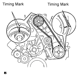
Turn the crankshaft clockwise and align the timing marks as shown in the illustration.
-
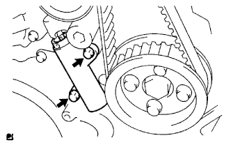
Uniformly loosen the 2 bolts and remove the timing belt tensioner.
-
Remove the timing belt.
-
Using a 10 mm hexagon wrench, remove the bolt, timing belt idler and washer.
Tech Tips
-
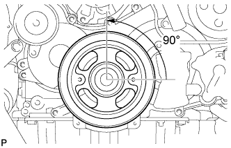
When turning the camshaft while the timing belt is removed, turn the crankshaft 90° counterclockwise.
-
When installing the timing belt, return the camshaft to the timing marks and then turn the crankshaft clockwise until it aligns with the timing marks, as shown in the illustration.
-
-
-
REMOVE NO. 1 TIMING BELT IDLER SUB-ASSEMBLY
-
REMOVE NO. 1 TIMING BELT TENSIONER ASSEMBLY
-
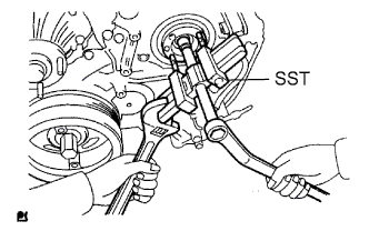
REMOVE CRANKSHAFT PULLEY
-
Using SST, remove the pulley bolt.
- SST
- 09213-58014
- 09330-00021
-
Using SST, remove the pulley.
- SST
- 09950-50013 ( 09951-05010, 09952-05010, 09953-05020, 09954-05021 )
Note
Apply oil or grease to the threads and tip of SST (center bolt) before using it.
-
-
REMOVE TURBOCHARGER SUB-ASSEMBLY (w/ EGR Cooler)
-
REMOVE TURBOCHARGER SUB-ASSEMBLY (w/o EGR Cooler)
-
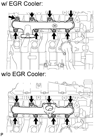
REMOVE EXHAUST MANIFOLD
-
w/o EGR Cooler:
Remove the 8 nuts, 8 spacers and exhaust manifold.
-
w/ EGR Cooler:
Remove the 8 nuts, 8 spacers, 8 collars and exhaust manifold.
-
-
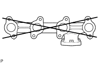
INSPECT EXHAUST MANIFOLD
-
Using a precision straightedge and feeler gauge, measure the surface contacting the cylinder head for warpage.
Maximum warpage 0.40 mm (0.0157 in.) If the warpage is more than the maximum, replace the exhaust manifold.
-
-
REMOVE GENERATOR ASSEMBLY
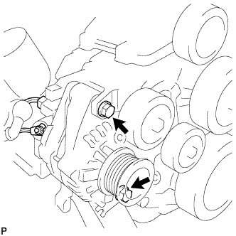
-
Remove the nut and generator wire.
-
Disconnect the generator connector.
-
Remove the 2 bolts and generator.
-
-
REMOVE GENERATOR BRACKET
-
Remove the bolt and generator bracket.
-
-
REMOVE V-RIBBED BELT TENSIONER ASSEMBLY
-
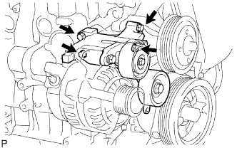
Remove the 4 bolts and V-ribbed belt tensioner.
-
-
REMOVE INTERCOOLER SUPPORT BRACKET (w/ EGR Cooler)
-
Remove the 2 bolts and intercooler support bracket.
-
-
REMOVE NO. 2 INTERCOOLER SUPPORT BRACKET (w/ EGR Cooler)
-
Remove the 2 bolts and No. 2 intercooler support bracket.
-
-
REMOVE NO. 1 COMPRESSOR MOUNTING BRACKET (w/ Air Conditioning System)
-
Remove the 4 bolts and No. 1 compressor mounting bracket.
-
-
REMOVE VISCOUS HEATER WITH MAGNET CLUTCH ASSEMBLY (w/ Viscous Heater)
-
Disconnect the connector.
-
Remove the 2 bolts and viscous with magnet clutch heater assembly.
-
-
REMOVE NO. 1 VISCOUS HEATER BRACKET SUB-ASSEMBLY (w/ Viscous Heater)
-
Remove the 4 bolts and No. 1 viscous heater bracket.
-
-
REMOVE WATER INLET
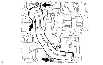
-
Remove the 3 bolts and water inlet.
-
-
REMOVE THERMOSTAT
-
REMOVE WATER OUTLET
-
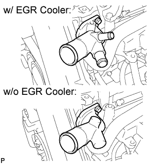
Remove the 2 bolts and water outlet.
-
-
REMOVE GLOW PLUG ASSEMBLY
-
w/ EGR Cooler:
-
w/ EGR System without EGR Cooler:
-
w/o EGR System:
-
-
REMOVE MANIFOLD STAY (w/o EGR Cooler)
-
Remove the 2 bolts and manifold stay.
-
-
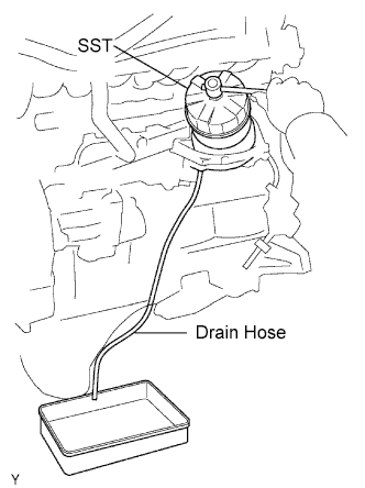
REMOVE OIL FILTER SUB-ASSEMBLY
-
Using SST, remove the oil filter.
- SST
- 09228-07501
Tech Tips
Insert the drain hose in the oil filter. Put the drain oil container beneath the drain hose to collect the oil from the oil filter.
-
-
REMOVE INTAKE MANIFOLD (w/ EGR Cooler)
-
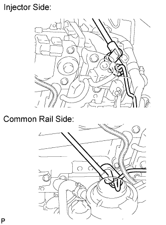
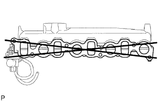
REMOVE NO. 1, NO. 2 AND NO. 3 INJECTION PIPE SUB-ASSEMBLY (w/o EGR Cooler)
Note
-
After removing the fuel pipe, cover the outlets on the common rail with tape to keep out foreign matter.
-
After removing the fuel pipe, put it in a plastic bag to prevent foreign matter from contaminating its injector inlet.
-
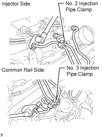
Remove the bolt and No. 2 injection pipe clamp.
-
Remove the 2 nuts and No. 3 injection pipe clamp.
-
Using a 17 mm union nut wrench, loosen the union nuts and remove the No. 1, No. 2 and No. 3 injection pipes.
-
-
REMOVE NO. 4 INJECTION PIPE SUB-ASSEMBLY (w/o EGR Cooler)
-
Remove the 2 bolts.
Note
If an injection pipe clamp is removed from the No. 4 injection pipe, replace the injection clamp with a new one.
-
Using a 17 mm union nut wrench, loosen the union nuts and remove the No. 4 injection pipe.
-
-
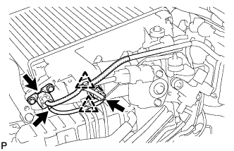
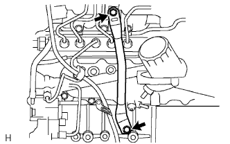
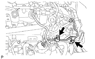
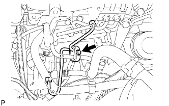
REMOVE NO. 2 NOZZLE LEAKAGE PIPE ASSEMBLY (w/o EGR Cooler)
-
Disconnect the 3 fuel hoses.
-
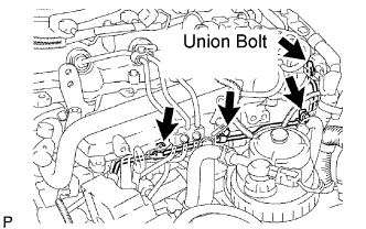
Remove the union bolt, 3 bolts, No. 2 nozzle leakage pipe and gasket.
-
-
REMOVE INTAKE MANIFOLD (w/o EGR Cooler)
-
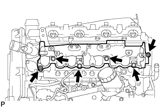
Remove the 4 bolts, 2 nuts, intake manifold and gasket.
-
-
INSPECT INTAKE MANIFOLD
-
Using a precision straightedge and feeler gauge, measure the surface contacting the cylinder head for warpage.
Maximum warpage 0.40 mm (0.0157 in.) If the warpage is more than the maximum, replace the intake manifold.
-
-
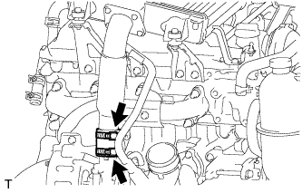
REMOVE FUEL SUPPLY PUMP ASSEMBLY
-
Remove the bolt and clamp.
-
Remove the 2 bolts and oil level gauge guide.
-
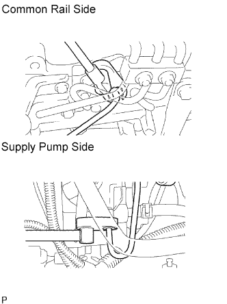
Using a 17 mm union nut wrench, loosen the union nuts and remove the fuel inlet pipe.
-
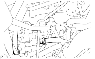
Disconnect the 2 fuel hoses.
-
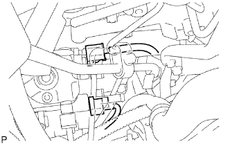
Disconnect the 2 connectors.
-
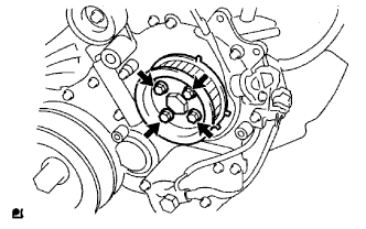
Remove the 4 bolts indicated by the arrows in the illustration.
-
Remove the No. 2 camshaft timing pulley flange and pump drive shaft pulley.
-
Remove the set nut and O-ring while holding the crankshaft pulley by using SST.
- SST
- 09213-58013
- 09330-00021
-
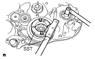
Loosen the 2 nuts.
-
Using SST, disconnect the pump from the injection gear.
- SST
- 09950-50013 ( 09951-05010, 09952-05010, 09953-05020, 09954-05021 )
Note
Apply lubricant to the threads and tip of SST (center bolt) before using it.
-
Remove the 2 nuts and pump.
Note
-
Do not hold the pump or carry it holding the pipe.
-
The pump must be kept horizontal.
-
-
Remove the O-ring.
-
-
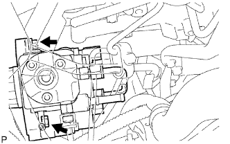
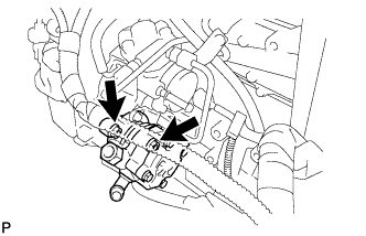
REMOVE COMMON RAIL ASSEMBLY
-
Disconnect the fuel pressure sensor connector and pressure discharge valve connector.
-
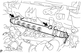
Remove the 2 bolts and common rail.
Note
Do not remove the fuel pressure sensor and pressure discharge valve.
-
-
REMOVE OIL COOLER COVER SUB-ASSEMBLY
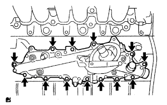
-
Disconnect the oil pressure switch connector and wire harness.
-
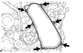
Remove the 13 bolts, 2 nuts and oil cooler cover.
-
-
REMOVE TIMING GEAR COVER INSULATOR (w/ EGR Cooler)
-
Remove the bolt and timing gear cover insulator.
-
-
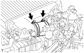
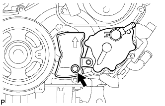
REMOVE VACUUM PUMP ASSEMBLY
-
Remove the 2 nuts, vacuum pump and 2 O-rings.
-
-
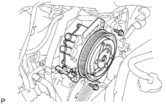
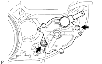
REMOVE VANE PUMP ASSEMBLY
-
Remove the 2 nuts, vane pump and O-ring.
-
-
REMOVE CRANKSHAFT POSITION SENSOR
-
Remove the bolt and crankshaft position sensor.
-
-
REMOVE CAMSHAFT POSITION SENSOR
-
Remove the bolt and camshaft position sensor.
-
-
REMOVE ENGINE COOLANT TEMPERATURE SENSOR
-
Using a 19 mm deep socket wrench, remove the engine coolant temperature sensor and gasket.
-
-
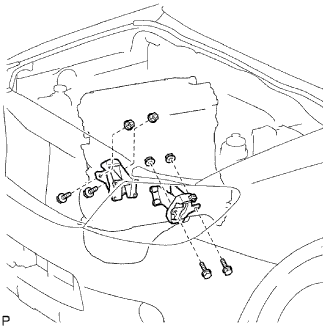
REMOVE FRONT ENGINE MOUNTING INSULATOR
-
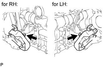
Remove the 2 nuts and 2 front engine mounting insulators.
-
-
REMOVE NO. 1 FRONT ENGINE MOUNTING BRACKET RH
-
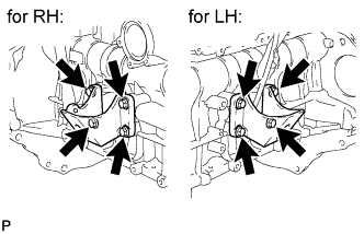
Remove the 4 bolts and No. 1 front engine mounting bracket.
-
-
REMOVE NO. 1 FRONT ENGINE MOUNTING BRACKET LH
-
Remove the 4 bolts and No. 1 front engine mounting bracket.
-