CYLINDER HEAD DISASSEMBLY

CAUTION / NOTICE / HINT
The necessary procedures (adjustment, calibration, initialization, or registration) that must be performed after parts are removed and installed, or replaced during engine unit removal/installation are shown below.
| Replaced Part or Performed Procedure | Necessary Procedure | Effect/Inoperative Function when Necessary Procedure not Performed | Link | |
|---|---|---|---|---|
| Disconnect cable from negative battery terminal | Memorize steering angle neutral point | LKA/LDA System | ||
| Intelligent clearance sonar system*2 | ||||
| Pre-crash safety system | ||||
| Lighting system (EXT)
|
||||
| Adaptive high beam system | ||||
| Parking Assist Monitor System (w/ Parallel Parking Assist Function) | ||||
| Parking Assist Monitor System (w/o Parallel Parking Assist Function) | ||||
| Panoramic view monitor system | ||||
| Initialize back door lock | Power door lock control system | |||
| Reset back door close position | Power back door system | |||
| Replacement of ECM | Perform Vehicle Identification Number (VIN) or frame number registration |
|
for 2GR-FKS (w/ Canister Pump Module): for 2GR-FKS (w/o Canister Pump Module) |
|
| ECU Communication ID Registration (Immobiliser system) | Engine start function | See Service Bulletin for the registration method. | ||
| Perform code registration (Immobiliser system) |
|
|||
| Replacement of ECM (If possible, read the transaxle compensation code from the previous ECM) |
Possible to read transaxle compensation code | Perform the following procedures in the order shown:
|
|
Click here for Initialization (U881E) Click here for Registration (U881E) Click here for Initialization (U881F) Click here for Registration (U881F) |
| Impossible to read transaxle compensation code | Perform the following procedures in the order shown:
|
|||
w/ Canister Pump Module |
Inspection After Repair |
|
||
w/o Canister Pump Module |
Inspection After Repair |
|
||
| Replacement of automatic transaxle assembly | Perform the following procedures in the order shown:
|
|
for U881E Initialization: for U881E Registration: for U881F Initialization: for U881F Registration: |
|
| Front wheel alignment adjustment |
|
|
||
| Suspension, tires, etc. (The vehicle height changes because of suspension or tire replacement) |
|
|
||
| Rear television camera assembly optical axis (Back camera position setting) | Parking assist monitor system (w/ Parallel Parking Assist Function) | for Initialization: for Calibration: |
||
| Parking assist monitor system (w/o Parallel Parking Assist Function) | for Initialization: for Calibration: |
|||
|
Panoramic view monitor system | for Initialization: for Calibration: |
||
| Initialize headlight ECU sub-assembly LH |
|
|||
*2: When performing learning using the GTS.
Click here Click here
PROCEDURE
-
REMOVE INTAKE VALVE
-
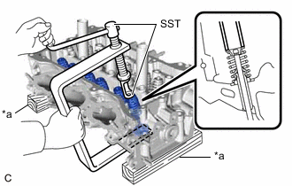
*a Wooden Block Using SST and wooden blocks, compress the inner compression spring and remove the 6 valve spring retainer locks from the valve spring retainer.
- SST
- 09202-70020 ( 09202-01010, 09202-01020 )
- 09202-00021
Tech Tips
Arrange the removed parts in such a way that they can be reinstalled to their original locations.
-
Remove the 6 valve spring retainers, 6 inner compression springs and 6 intake valves from the cylinder head LH.
Tech Tips
Arrange the removed parts in such a way that they can be reinstalled to their original locations.
-
-
REMOVE EXHAUST VALVE
-
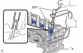
*a Wooden Block Using SST and wooden blocks, compress the inner compression spring and remove the 6 valve spring retainer locks from the valve spring retainer.
- SST
- 09202-70020 ( 09202-01010, 09202-01020 )
- 09202-00021
Tech Tips
Arrange the removed parts in such a way that they can be reinstalled to their original locations.
-
Remove the 6 valve spring retainers, 6 inner compression springs and 6 exhaust valves from the cylinder head LH.
Tech Tips
Arrange the removed parts in such a way that they can be reinstalled to their original locations.
-
-
REMOVE INTAKE VALVE STEM OIL SEAL
-
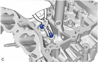
Using needle-nose pliers, remove the 6 intake valve stem oil seals from the intake valve guide bush.
-
-
REMOVE EXHAUST VALVE STEM OIL SEAL
Tech Tips
Use the same procedure as for the intake side.
-
REMOVE VALVE SPRING SEAT
-
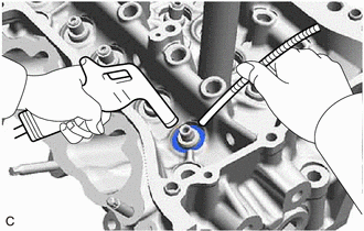
Using compressed air and a Magnet Hand, remove the 12 valve spring seats by blowing air onto them from the cylinder head LH.
Tech Tips
Arrange the removed parts in such a way that they can be reinstalled to their original locations.
-
-
REMOVE NO. 1 STRAIGHT SCREW PLUG
Note
If coolant leaks from a No. 1 straight screw plug or a plug is corroded, replace it.
-
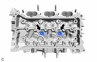
Using a 10 mm hexagon socket wrench, remove the 2 No. 1 straight screw plugs and 2 water hole gaskets from the cylinder head LH.
-
-
REMOVE NO. 2 STRAIGHT SCREW PLUG
Note
If coolant leaks from a No. 2 straight screw plug or a plug is corroded, replace it.
-
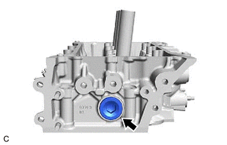
Using a 14 mm hexagon socket wrench, remove the No. 2 straight screw plug and cylinder head screw plug gasket from the cylinder head LH.
-
-
REMOVE NO. 3 STRAIGHT SCREW PLUG
Note
If coolant leaks from a No. 3 straight screw plug or a plug is corroded, replace it.
-
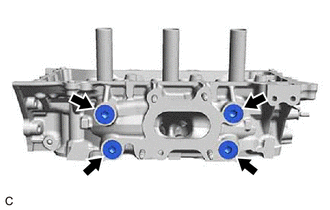
Using a 10 mm hexagon socket wrench, remove the 4 No. 3 straight screw plugs and 4 cylinder head screw plug gaskets from the cylinder head LH.
-