POWER STEERING ECU REMOVAL
CAUTION / NOTICE / HINT
The necessary procedures (adjustment, calibration, initialization, or registration) that must be performed after parts are removed, installed, or replaced during the power steering ECU assembly removal/installation are shown below.
| Replacement Part or Procedure | Necessary Procedures | Effects / Inoperative when not performed | Link |
|---|---|---|---|
| Replacement of the power steering ECU assembly |
|
|
|
| Replacement of the electric power steering column sub-assembly | Perform Torque Sensor Zero Point Calibration | ||
| Replacement of the steering lock actuator or upper bracket assembly | Perform code registration (Immobiliser system) |
|
See Service Bulletin for the registration method. |
| Removal/installation of the spiral cable with sensor sub-assembly |
|
Parking assist monitor system (w/ Parallel Parking Assist Function) | Click here for Initialization Click here for Calibration |
| Parking assist monitor system (w/o Parallel Parking Assist Function) | Click here for Initialization Click here for Calibration |
||
| Steering angle neutral point (Initialize panoramic view monitor system) | Panoramic view monitor system | Click here for Initialization Click here for Calibration |
|
| Steering angle neutral point (Initialize intelligent clearance sonar system) | Intelligent clearance sonar system | ||
| Disconnect cable from negative battery terminal | Memorize steering angle neutral point | LKA /LDA system | |
| Intelligent clearance sonar system*1 | |||
| Pre-crash safety system | |||
| Lighting system (EXT)
|
|||
| Adaptive high beam system | |||
| Parking Assist Monitor System (w/ Parallel Parking Assist Function) | |||
| Parking Assist Monitor System (w/o Parallel Parking Assist Function) | |||
| Panoramic view monitor system | |||
| Drive the vehicle until stop and start control is permitted (approximately 15 to 60 minutes) | Stop and start system | ||
| Initialize back door lock | Power door lock control system | ||
| Reset back door close position | Power back door system |
Click here Click here
PROCEDURE
-
REMOVE STEERING COLUMN ASSEMBLY
-
REMOVE STEERING LOCK ACTUATOR OR UPPER BRACKET ASSEMBLY
-
REMOVE POWER STEERING ECU ASSEMBLY
Note
-
Do not drop the power steering ECU assembly, strike it with tools or subject it to impacts.
-
If the power steering ECU assembly is subjected to an impact, replace it with a new one.
-
Do not pull the wire harness of the power steering ECU assembly.
-
Do not allow any moisture to come into contact with the power steering ECU assembly.
-
Do not loosen any bolts not mentioned in the procedure.
-
Do not allow any foreign matter to contaminate the power steering ECU assembly.
-
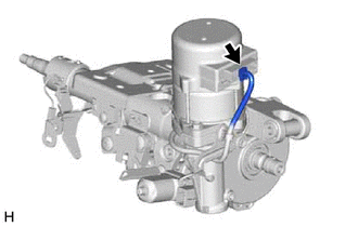
Disconnect the connector.
-
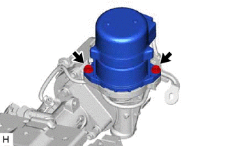
Remove the 2 bolts and power steering ECU assembly from the electric power steering column sub-assembly.
-
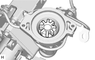
Remove the electric power steering motor shaft damper from the electric power steering column sub-assembly.
-