REAR TRAILING ARM REMOVAL
CAUTION / NOTICE / HINT
The necessary procedures (adjustment, calibration, initialization, or registration) that must be performed after parts are removed and installed, or replaced during rear trailing arm assembly removal/installation are shown below.
| Replaced Part or Performed Procedure | Necessary Procedure | Effect/Inoperative Function when Necessary Procedure not Performed | Link |
|---|---|---|---|
| Rear wheel alignment adjustment |
|
|
Tech Tips
-
Use the same procedure for the RH side and LH side.
-
The following procedure is for the LH side.
PROCEDURE
-
REMOVE REAR WHEEL
-
REMOVE REAR FLOOR SIDE MEMBER COVER LH (for 2WD)
-
REMOVE REAR FLOOR SIDE MEMBER COVER RH (for 2WD)
-
REMOVE REAR FLOOR SIDE MEMBER COVER LH (for AWD)
-
REMOVE REAR FLOOR SIDE MEMBER COVER RH (for AWD)
-
SEPARATE NO. 2 PARKING BRAKE WIRE ASSEMBLY
-
for 2WD:
-
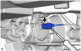
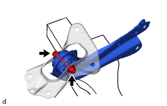
Using a screwdriver with its tip wrapped in protective tape, disconnect the No. 2 parking brake wire connector from the rear axle hub and bearing assembly.
Note
Be careful not to damage the rear axle hub and bearing assembly and connector cover.
-
-
for AWD:
-
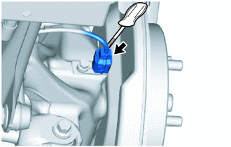
Using a screwdriver with its tip wrapped in protective tape, disconnect the No. 2 parking brake wire connector from the rear axle hub and bearing assembly.
Note
Be careful not to damage the rear axle hub and bearing assembly and connector cover.
-
-
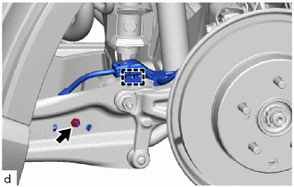
Disengage the clamp.
-
Remove the nut to separate the No. 2 parking brake wire assembly from the rear trailing arm assembly.
-
-
REMOVE REAR STABILIZER LINK ASSEMBLY
-
REMOVE REAR TRAILING ARM ASSEMBLY
-
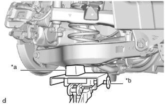
*a Wooden Block *b Transmission Jack Using a transmission jack and a wooden block, support the rear No. 2 suspension arm assembly.
Note
-
When jacking up the rear No. 2 suspension arm assembly, be sure to jack it up slowly.
-
Make sure to perform this operation with the vehicle kept as low as possible.
-
-
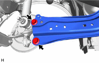
Remove the 2 bolts to separate the rear trailing arm assembly from the rear axle carrier sub-assembly.
-
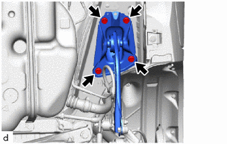
Remove the 4 bolts and rear trailing arm assembly.
-
-
REMOVE NO. 1 REAR SUSPENSION SUPPORT COVER
-
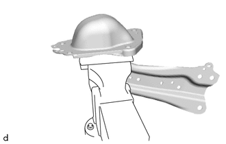
Secure the rear trailing arm assembly in a vise using aluminum plates.
Note
Do not overtighten the vise.
-
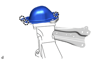
Disengage the 3 claws to remove the NO. 1 rear suspension support cover.
-
-
REMOVE REAR SUSPENSION ARM BRACKET
-
Remove the bolt, nut and rear suspension arm bracket from the rear trailing arm assembly.
Note
Because the bolt has its own stopper, do not turn the bolt. Loosen the nut with the bolt secured.
-