DYNAMIC RADAR CRUISE CONTROL SYSTEM Cruise Control Switch Circuit
DESCRIPTION
The cruise control main switch is used to turn the dynamic radar cruise control system on and off, as well as operate 7 functions: SET, - (COAST), TAP-DOWN, RES (RESUME), + (ACCEL), TAP-UP and CANCEL.
The SET, TAP-DOWN and - (COAST) functions, and the RES (RESUME), TAP-UP and + (ACCEL) functions are operated with the same switch. The cruise control main switch contains momentary type contacts for each function. The contacts close only while the cruise control main switch is being operated in the direction of the relative function arrow, and open when the cruise control main switch is released. The voltage at the terminal of the hybrid vehicle control ECU assembly changes as each of the different contacts open or close. The hybrid vehicle control ECU assembly reads this voltage and controls the SET, - (COAST), RES (RESUME), + (ACCEL), and CANCEL functions accordingly.
-
Vehicle-to-vehicle distance control mode is selected by default when the dynamic radar cruise control system is turned on using the cruise control main switch (ON/OFF button).
-
The operation of constant speed control mode is the same as that for a conventional cruise control system.
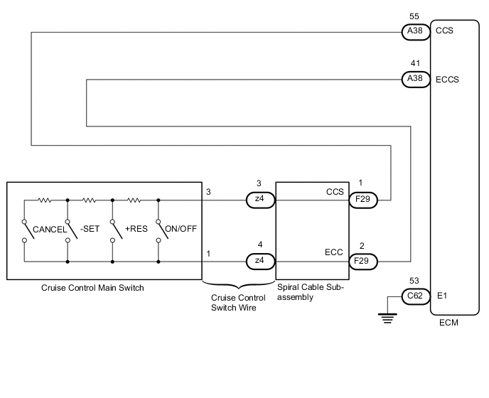
WIRING DIAGRAM
CAUTION / NOTICE / HINT
Note
-
Before replacing the ECM refer to Service Bulletin.
-
The vehicle is equipped with a Supplemental Restraint System (SRS) which includes components such as airbags. Before servicing (including removal or installation of parts), be sure to read the precaution for Supplemental Restraint System.
-
When replacing the millimeter wave radar sensor assembly, always replace it with a new one. If a millimeter wave radar sensor assembly which was installed to another vehicle is used, the information stored in the millimeter wave radar sensor assembly will not match the information from the vehicle. As a result, a DTC may be stored.
PROCEDURE
-
READ VALUE USING GTS
-
Connect the GTS to the DLC3.
-
Turn the ignition switch to ON.
-
Turn the GTS on.
-
Enter the following menus: Powertrain / Cruise Control / Data List.
-
Read the Data List according to the display on the GTS.
Powertrain > Cruise Control > Data ListTester Display Measurement Item Range Normal Condition Diagnostic Note -SET Switch -SET switch signal ON or OFF ON: -SET switch on
OFF: -SET switch off
- +RES Switch +RES switch signal ON or OFF ON: +RES switch on
OFF: +RES switch off
- Cruise Main Switch Operation Condition Cruise control main switch (ON/OFF button) status ON or OFF ON: Cruise control main switch (ON/OFF button) pushed
OFF: Cruise control main switch (ON/OFF button) not pushed
-
Powertrain > Cruise Control > Data ListTester Display -SET Switch +RES Switch Cruise Main Switch Operation Condition OK The Data List items shown in the table change according to the operation of the cruise control main switch. Result Proceed to OK NG
OK 
PROCEED TO NEXT SUSPECTED AREA SHOWN IN PROBLEM SYMPTOMS TABLE Click here
NG 
-
-
INSPECT CRUISE CONTROL MAIN SWITCH
-
Remove the cruise control main switch.
-
Inspect the cruise control main switch.
Result Proceed to OK NG
NG
REPLACE CRUISE CONTROL MAIN SWITCH Click here
OK
-
-
CHECK CRUISE CONTROL SWITCH WIRE
-
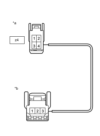
*a Front view of wire harness connector
(to Spiral Cable Sub-assembly)
*b Front view of wire harness connector
(to Cruise Control Main Switch)
Remove the cruise control switch wire.
-
Measure the resistance according to the value(s) in the table below.
Standard Resistance (Check for Open) Tester Connection Specified Condition Cruise control main switch side connector terminal 3 - z4-3 Below 1 Ω Cruise control main switch side connector terminal 1 - z4-4 Below 1 Ω Result Proceed to OK NG
NG
REPLACE CRUISE CONTROL SWITCH WIRE Click here
OK
-
-
INSPECT SPIRAL CABLE SUB-ASSEMBLY
-
Remove the spiral cable sub-assembly.
-
Inspect the spiral cable sub-assembly.
Result Proceed to OK NG
NG
REPLACE SPIRAL CABLE SUB-ASSEMBLY Click here
OK
-
-
CHECK HARNESS AND CONNECTOR (SPIRAL CABLE SUB-ASSEMBLY - ECM AND BODY GROUND)
-
Disconnect the spiral cable sub-assembly connector.
-
Disconnect the ECM connector.
-
Measure the resistance according to the value(s) in the table below.
Standard Resistance Tester Connection Condition Specified Condition F29-1 (CCS) - A38-55 (CCS) Always Below 1 Ω F29-2 (ECC) - A38-41 (ECCS) Always Below 1 Ω F29-1 (CCS) or A38-55 (CCS) - Body ground Always 10 kΩ or higher F29-2 (ECC) or A38-41 (ECCS) - Body ground Always 10 kΩ or higher Result Proceed to OK NG
NG
REPAIR OR REPLACE HARNESS OR CONNECTOR
OK
-
-
CHECK HARNESS AND CONNECTOR (ECM - BODY GROUND)
-
Disconnect the ECM connector.
-
Measure the resistance according to the value(s) in the table below.
Standard Resistance Tester Connection Condition Specified Condition F29-2 (ECC) or C62-53 (E1) - Body ground Always Below 1 Ω Result Proceed to OK NG
OK
REPLACE ECM Click here
NG
REPAIR OR REPLACE HARNESS OR CONNECTOR
-