PANORAMIC VIEW MONITOR SYSTEM Image from Camera for Panoramic View Monitor is Abnormal
DESCRIPTION
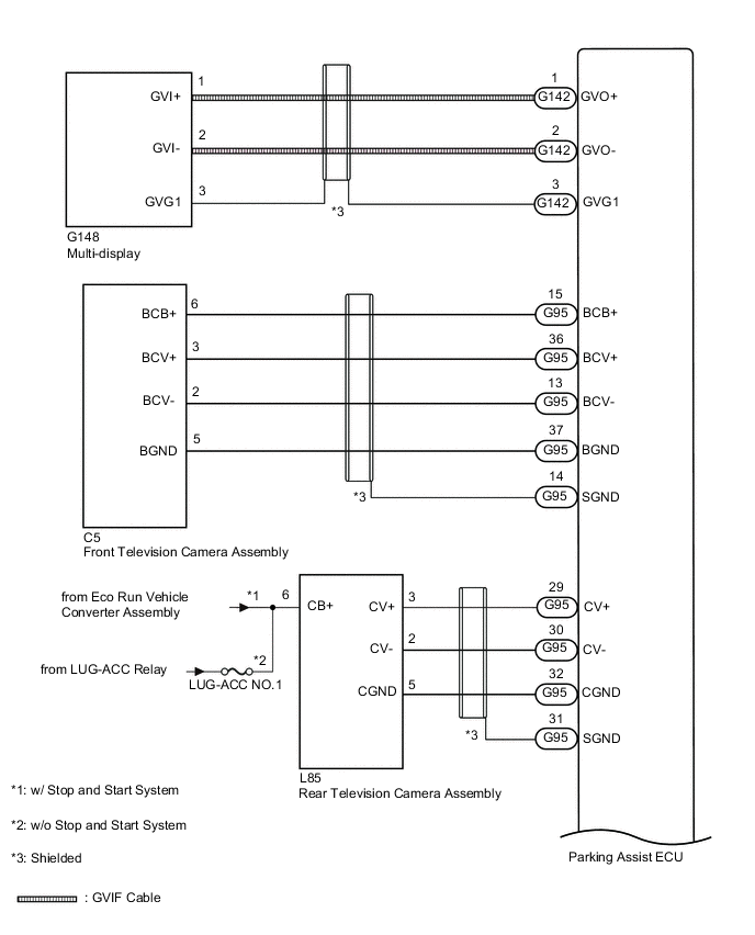
The display signal from each camera is transmitted to the multi-display via the parking assist ECU.
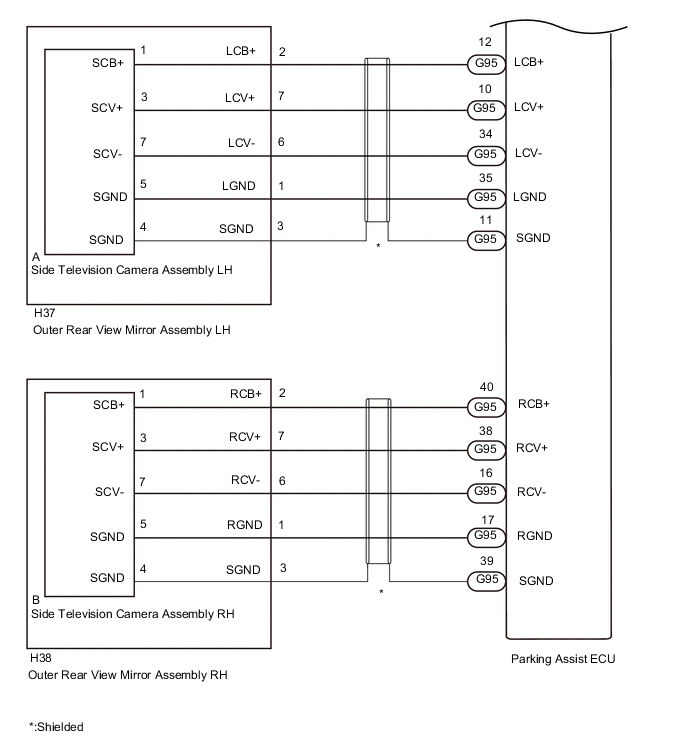
WIRING DIAGRAM
CAUTION / NOTICE / HINT
Note
-
When "!" mark is displayed on the multi-display after the battery terminal has been disconnected, correct the steering angle neutral point.
-
Depending on the parts that are replaced or operations that are performed during vehicle inspection or maintenance, calibration of other systems as well as the panoramic view monitor system may be needed.
Tech Tips
-
Electrical devices are used in the cabin (noise may occur in the image).
-
The camera lens is frosted over (the image immediately after turning the engine switch on (IG) may be blurred or darker than normal).
-
The camera lens is dirty with snow, mud, etc.
-
A strong beam of light, such as a sunbeam or headlight, hits the camera.
-
It is too dark around the camera (at night, etc.).
-
The ambient temperature around the camera is either too high or too low.
-
The vehicle is tilted at a steep angle.
-
The television camera assembly lens is scratched.
-
The television camera assembly lens has drops of water on it or the humidity is high.
-
When the camera is used under fluorescent lights, sodium lights, or mercury lights, etc., the lights and the illuminated area may appear to flicker.
Images may be unclear even in normal conditions if:
-
w/o Stop and Start System:
Inspect the fuses for circuits related to this system before performing the following procedure.
-
w/ Stop and Start System:
The panoramic view monitor system troubleshooting procedure is based on the premise that the stop and start system normally. Check the stop and start system first before troubleshooting the panoramic view monitor system.
for 8GR-FKS:
for V35A-FTS:
PROCEDURE
-
CHECK PANORAMIC VIEW MONITOR SYSTEM
-
Check if the same malfunction occurs when the panoramic view monitor screen is displayed.
Result Result Proceed to Rear view screen is not displayed. A Front view screen is not displayed. B Side monitor screen (LH side) is not displayed. C Side monitor screen (RH side) is not displayed. D Panoramic view monitor screen is not displayed. E
B 
CHECK HARNESS AND CONNECTOR (PARKING ASSIST ECU - FRONT TELEVISION CAMERA ASSEMBLY) Click here
C
CHECK HARNESS AND CONNECTOR (PARKING ASSIST ECU - OUTER REAR VIEW MIRROR ASSEMBLY LH) Click here
D
CHECK HARNESS AND CONNECTOR (PARKING ASSIST ECU - OUTER REAR VIEW MIRROR ASSEMBLY RH) Click here
E
CHECK HARNESS AND CONNECTOR (GVIF CABLE) Click here
A 
-
-
CHECK HARNESS AND CONNECTOR (PARKING ASSIST ECU - REAR TELEVISION CAMERA ASSEMBLY)
-
Disconnect the G95 parking assist ECU connector.
-
Disconnect the L85 rear television camera assembly connector.
-
Measure the resistance according to the value(s) in the table below.
Standard Resistance Tester Connection Condition Specified Condition G95-30 (CV-) - L85-2 (CV-) Always Below 1 Ω G95-32 (CGND) - L85-5 (CGND) Always Below 1 Ω G95-29 (CV+) or L85-3 (CV+) - Body ground Always 10 kΩ or higher G95-30 (CV-) or L85-2 (CV-) - Body ground Always 10 kΩ or higher G95-32 (CGND) or L85-5 (CGND) - Body ground Always 10 kΩ or higher G95-31 (SGND) - Body ground Always 10 kΩ or higher -
Measure the voltage according to the value(s) in the table below.
Standard Voltage Tester Connection Switch Condition Specified Condition G95-29 (CV+) or L85-3 (CV+) - Body ground Engine switch on (IG) Below 1 V G95-29 (CV+) or L85-3 (CV+) - Body ground Engine switch on (IG) Below 1 V G95-32 (CGND) or L85-5 (CGND) - Body ground Engine switch on (IG) Below 1 V G95-31 (SGND) - Body ground Engine switch on (IG) Below 1 V Result Proceed to OK NG
NG 
REPAIR OR REPLACE HARNESS OR CONNECTOR
OK
-
-
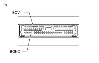
CHECK PARKING ASSIST ECU (CV-, CGND)
-
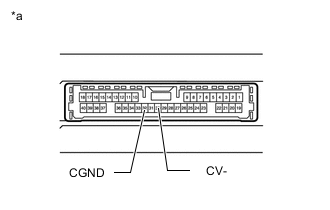
*a Component without harness connected
(Parking Assist ECU)
Disconnect the G95 parking assist ECU.
-
Measure the resistance according to the value(s) in the table below.
Standard Resistance Tester Connection Condition Specified Condition 30 (CV-) - Body ground Always Below 1 Ω 32 (CGND) - Body ground Always Below 1 Ω Result Proceed to OK NG
NG
REPLACE PARKING ASSIST ECU Click here
OK
-
-
CHECK REAR TELEVISION CAMERA ASSEMBLY (CB+, BODY GROUND)
-
Disconnect the L85 rear television camera assembly.
-
Measure the voltage according to the value(s) in the table below.
Standard Voltage Tester Connection Switch Condition Specified Condition L85-6(CB+) - Body ground Engine switch on (IG) 10.5 to 16 V*1
11 to 14 V*2
Engine switch off Below 1 V
-
*1: w/ Stop and Start System
-
*2: w/o Stop and Start System
Result Proceed to OK NG -
NG
REPAIR OR REPLACE HARNESS OR CONNECTOR
OK
-
-
CHECK REAR TELEVISION CAMERA ASSEMBLY (CV+, CGND)
-
Remove the parking assist ECU with the connector still connected.
-
Using an oscilloscope, check the waveform of the rear television camera assembly.
Tech Tips
A waterproof connector is used for the rear television camera assembly. Therefore, inspect the waveform at the parking assist ECU with the connector connected.
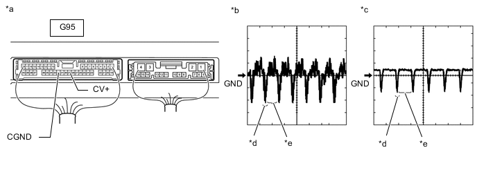
*a Component with harness connected
(Parking Assist ECU)
*b Waveform 1 (camera lens not covered, displaying an image) *c Waveform 2 (camera lens covered, blacking out the screen) *d Synchronization Signal *e Video Waveform - - Tech Tips
-
The video waveform changes according to the image sent by the rear television camera assembly.
-
The video waveform is constantly output when the engine switch is on (ACC).
Measurement Condition Tester Connection Condition Tool Setting G95-29 (CV+) - G95-32 (CGND) Engine switch on (IG), panoramic view monitor switch on 200 mV/DIV., 50 μsec./DIV. OK Waveform is similar to that shown in the illustration. Result Proceed to OK NG -
OK
REPLACE PARKING ASSIST ECU Click here
NG
REPLACE REAR TELEVISION CAMERA ASSEMBLY Click here
-
-
CHECK HARNESS AND CONNECTOR (PARKING ASSIST ECU - FRONT TELEVISION CAMERA ASSEMBLY)
-
Disconnect the G95 parking assist ECU connector.
-
Disconnect the C5 front television camera assembly connector.
-
Measure the resistance according to the value(s) in the table below.
Standard Resistance Tester Connection Condition Specified Condition G95-15 (BCB+) - C5-6 (BCB+) Always Below 1 Ω G95-36 (BCV+) - C5-3 (BCV+) Always Below 1 Ω G95-13 (BCV-) - C5-2 (BCV-) Always Below 1 Ω G95-37 (BGND) - C5-5 (BGND) Always Below 1 Ω G95-15 (BCB+) or C5-6 (BCB+) - Body ground Always 10 kΩ or higher G95-36 (BCV+) or C5-3 (BCV+) - Body ground Always 10 kΩ or higher G95-13 (BCV-) or C5-2 (BCV-) - Body ground Always 10 kΩ or higher G95-37 (BGND) or C5-5 (BGND) - Body ground Always 10 kΩ or higher G95-14 (SGND) - Body ground Always 10 kΩ or higher -
Measure the voltage according to the value(s) in the table below.
Standard Voltage Tester Connection Switch Condition Specified Condition G95-15(BCB+) or C5-6(BCB+) - Body ground Engine switch on (IG) Below 1 V G95-36(BCV+) or C5-3(BCV+) - Body ground Engine switch on (IG) Below 1 V G95-13(BCV-) or C5-2(BCV-) - Body ground Engine switch on (IG) Below 1 V G95-37(BGND) or C5-5(BGND) - Body ground Engine switch on (IG) Below 1 V G95-14 (SGND) - Body ground Engine switch on (IG) Below 1 V Result Proceed to OK NG
NG
REPAIR OR REPLACE HARNESS OR CONNECTOR
OK
-
-
CHECK PARKING ASSIST ECU (BCB+, BGND)
-
*a Component without harness connected
(Parking Assist ECU)
Disconnect the G95 parking assist ECU.
-
Measure the resistance according to the value(s) in the table below.
Standard Resistance Tester Connection Condition Specified Condition 37 (BGND) - Body ground Always Below 1 Ω 13 (BCV-) - Body ground Always Below 1 Ω Result Proceed to OK NG
NG
REPLACE PARKING ASSIST ECU Click here
OK
-
-
CHECK PARKING ASSIST ECU (BCB+, BGND)
-
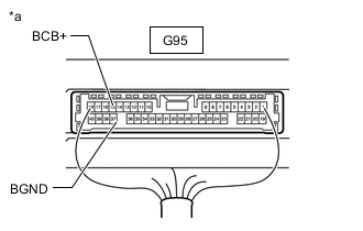
*a Component with harness connected
(Parking Assist ECU)
Disconnect the front television camera assembly connector.
-
Measure the voltage according to the value(s) in the table below.
Standard Voltage Tester Connection Switch Condition Specified Condition G95-15 (BCB+) - G95-37 (BGND) Engine switch on (IG) 5.5 to 7.05 V G95-15 (BCB+) - G95-37 (BGND) Engine switch off Below 1 V Result Proceed to OK NG
NG
REPLACE PARKING ASSIST ECU Click here
OK
-
-
CHECK FRONT TELEVISION CAMERA ASSEMBLY (BCV+, BGND)
-
Remove the parking assist ECU with the connector still connected.
-
Using an oscilloscope, check the waveform of the front television camera assembly.
Tech Tips
A waterproof connector is used for the front television camera assembly. Therefore, inspect the waveform at the parking assist ECU with the connector connected.
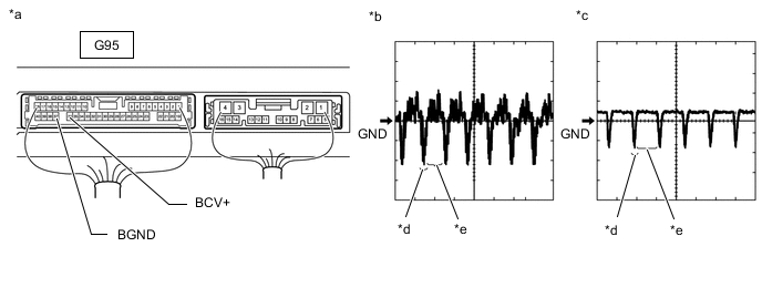
*a Component with harness connected
(Parking Assist ECU)
*b Waveform 1 (camera lens not covered, displaying an image) *c Waveform 2 (camera lens covered, blacking out the screen) *d Synchronization Signal *e Video Waveform - - Tech Tips
-
The video waveform changes according to the image sent by the front television camera assembly.
-
The video waveform is constantly output when the engine switch is on (ACC).
Measurement Condition Tester Connection Condition Tool Setting G95-36 (BCV+) - G95-37 (BGND) Engine switch on (IG), panoramic view monitor switch on 200 mV/DIV., 50 μsec./DIV. OK Waveform is similar to that shown in the illustration. Result Proceed to OK NG -
OK
REPLACE PARKING ASSIST ECU Click here
NG
REPLACE FRONT TELEVISION CAMERA ASSEMBLY Click here
-
-
CHECK HARNESS AND CONNECTOR (PARKING ASSIST ECU - OUTER REAR VIEW MIRROR ASSEMBLY LH)
-
Disconnect the G95 parking assist ECU connector.
-
Disconnect the H37 outer rear view mirror assembly LH connector.
-
Measure the resistance according to the value(s) in the table below.
Standard Resistance Tester Connection Condition Specified Condition G95-12 (LCB+) - H37-2 (LCB+) Always Below 1 Ω G95-10 (LCV+) - H37-7 (LCV+) Always Below 1 Ω G95-34 (LCV-) - H37-6 (LCV-) Always Below 1 Ω G95-35 (LGND) - H37-1 (LGND) Always Below 1 Ω G95-12 (LCB+) or H37-2 (LCB+) - Body ground Always 10 kΩ or higher G95-10 (LCV+) or H37-7 (LCV+) - Body ground Always 10 kΩ or higher G95-34 (LCV-) or H37-6 (LCV-) - Body ground Always 10 kΩ or higher G95-35 (LGND) or H37-1 (LGND) - Body ground Always 10 kΩ or higher G95-35 (LGND) - Body ground Always 10 kΩ or higher -
Measure the voltage according to the value(s) in the table below.
Standard Voltage Tester Connection Switch Condition Specified Condition G95-12(LCB+) or H37-2(LCB+) - Body ground Engine switch on (IG) Below 1 V G95-10(LCV+) or H37-7(LCV+) - Body ground Engine switch on (IG) Below 1 V G95-34(LCV-) or H37-6(LCV-) - Body ground Engine switch on (IG) Below 1 V G95-35(LGND) or H37-1(LGND) - Body ground Engine switch on (IG) Below 1 V G95-11(SGND) or H37-3(SGND) - Body ground Engine switch on (IG) Below 1 V Result Proceed to OK NG
NG
REPAIR OR REPLACE HARNESS OR CONNECTOR
OK
-
-
CHECK PARKING ASSIST ECU (LCV-, LGND)
-
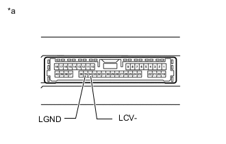
*a Component without harness connected
(Parking Assist ECU)
Disconnect the G95 parking assist ECU.
-
Measure the resistance according to the value(s) in the table below.
Standard Resistance Tester Connection Condition Specified Condition 35 (LGND) - Body ground Always Below 1 Ω 34 (LCV-) - Body ground Always Below 1 Ω Result Proceed to OK NG
NG
REPLACE PARKING ASSIST ECU Click here
OK
-
-
CHECK PARKING ASSIST ECU (LCB+, LGND)
-
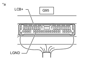
*a Component with harness connected
(Parking Assist ECU)
Disconnect the outer rear view mirror assembly LH connector.
-
Measure the voltage according to the value(s) in the table below.
Standard Voltage Tester Connection Switch Condition Specified Condition G95-12 (LCB+) - G95-35 (LGND) Engine switch on (IG) 5.5 to 7.05 V G95-12 (LCB+) - G95-35 (LGND) Engine switch off Below 1 V Result Proceed to OK NG
NG
REPLACE PARKING ASSIST ECU Click here
OK
-
-
CHECK SIDE TELEVISION CAMERA ASSEMBLY LH (LCV+, LGND)
-
Remove the parking assist ECU with the connector still connected.
-
Using an oscilloscope, check the waveform of the side television camera assembly LH.
Tech Tips
A waterproof connector is used for the side television camera assembly LH. Therefore, inspect the waveform at the parking assist ECU with the connector connected.
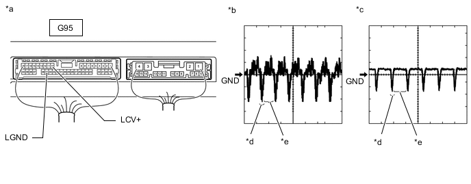
*a Component with harness connected
(Parking Assist ECU)
*b Waveform 1 (camera lens not covered, displaying an image) *c Waveform 2 (camera lens covered, blacking out the screen) *d Synchronization Signal *e Video Waveform - - Tech Tips
-
The video waveform changes according to the image sent by the side television camera assembly LH.
-
The video waveform is constantly output when the engine switch is on (ACC).
Measurement Condition Tester Connection Condition Tool Setting G95-10 (LCV+) - G95-35 (LGND) Engine switch on (IG), panoramic view monitor switch on 200 mV/DIV., 50 μsec./DIV. OK Waveform is similar to that shown in illustration. Result Proceed to OK NG -
OK
REPLACE PARKING ASSIST ECU Click here
NG
-
-
INSPECT OUTER REAR VIEW MIRROR ASSEMBLY LH
-
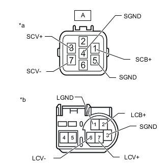
*a Component without harness connected
(to Side Television Camera Assembly LH)
*b Component without harness connected
(to Outer Rear View Mirror Assembly LH)
Disconnect the outer rear view mirror assembly LH connector.
-
Disconnect the side television camera assembly LH connector.
-
Measure the resistance according to the value(s) in the table below.
Standard Resistance Tester Connection Condition Specified Condition A-1 (SCB+) - 2 (LCB+) Always Below 1 Ω A-3 (SCV+) - 7 (LCV+) Always Below 1 Ω A-4(SGND) - 3(SGND) Always Below 1 Ω A-7 (SCV-) - 6 (LCV-) Always Below 1 Ω A-5 (SGND) - 1 (LGND) Always Below 1 Ω A-1 (SCB+) or 2 (LCB+) - Body ground Always 10 kΩ or higher A-3 (SCV+) or 7 (LCV+) - Body ground Always 10 kΩ or higher A-4(SGND) or 3(SGND) - Body ground Always 10 kΩ or higher A-7 (SCV-) or 6 (LCV-) - Body ground Always 10 kΩ or higher A-5 (SGND) or 1 (LGND) - Body ground Always 10 kΩ or higher Result Proceed to OK NG
NG
REPLACE OUTER REAR VIEW MIRROR ASSEMBLY LH Click here
OK
-
-
CHECK SIDE TELEVISION CAMERA ASSEMBLY LH
-
Replace the side television camera assembly LH with a new or normally functioning one.
-
Check if the same malfunction reoccurs when the side monitor screen is displayed.
Result Result Proceed to Malfunction does not reoccur (returns to normal) A Malfunction reoccurs B
A
END (SIDE TELEVISION CAMERA ASSEMBLY LH IS DEFECTIVE)
B
REPLACE PARKING ASSIST ECU Click here
-
-
CHECK HARNESS AND CONNECTOR (PARKING ASSIST ECU - OUTER REAR VIEW MIRROR ASSEMBLY RH)
-
Disconnect the G95 parking assist ECU connector.
-
Disconnect the H38 outer rear view mirror assembly RH connector.
-
Measure the resistance according to the value(s) in the table below.
Standard Resistance Tester Connection Condition Specified Condition G95-40 (RCB+) - H38-2 (RCB+) Always Below 1 Ω G95-38 (RCV+) - H38-7 (RCV+) Always Below 1 Ω G95-16 (RCV-) - H38-6 (RCV-) Always Below 1 Ω G95-17 (RGND) - H38-1 (RGND) Always Below 1 Ω G95-40 (RCB+) or H38-2 (RCB+) - Body ground Always 10 kΩ or higher G95-38 (RCV+) or H38-7 (RCV+) - Body ground Always 10 kΩ or higher G95-16 (RCV-) or H38-6 (RCV-) - Body ground Always 10 kΩ or higher G95-17 (RGND) or H38-1 (RGND) - Body ground Always 10 kΩ or higher G95-39 (SGND) or H38-3 (SGND) - Body ground Always 10 kΩ or higher -
Measure the voltage according to the value(s) in the table below.
Standard Voltage Tester Connection Switch Condition Specified Condition G95-40 (RCB+) or H38-2 (RCB+) - Body ground Engine switch on (IG) Below 1 V G95-38 (RCV+) or H38-7 (RCV+) - Body ground Engine switch on (IG) Below 1 V G95-16 (RCV-) or H38-6 (RCV-) - Body ground Engine switch on (IG) Below 1 V G95-17 (RGND) or H38-1 (RGND) - Body ground Engine switch on (IG) Below 1 V G95-39 (SGND) or H38-3 (SGND) - Body ground Engine switch on (IG) Below 1 V Result Proceed to OK NG
NG
REPAIR OR REPLACE HARNESS OR CONNECTOR
OK
-
-
CHECK PARKING ASSIST ECU (RCV-, RGND)
-
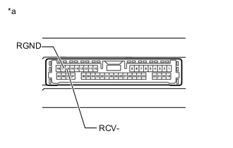
*a Component without harness connected
(Parking Assist ECU)
Disconnect the G95 parking assist ECU.
-
Measure the resistance according to the value(s) in the table below.
Standard Resistance Tester Connection Condition Specified Condition 17 (RGND) - Body ground Always Below 1 Ω 16 (RCV-) - Body ground Always Below 1 Ω Result Proceed to OK NG
NG
REPLACE PARKING ASSIST ECU Click here
OK
-
-
CHECK PARKING ASSIST ECU (RCB+, RGND)
-
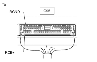
*a Component with harness connected
(Parking Assist ECU)
Disconnect the outer rear view mirror assembly RH connector.
-
Measure the voltage according to the value(s) in the table below.
Standard Voltage Tester Connection Switch Condition Specified Condition G95-40 (RCB+) - G95-17 (RGND) Engine switch on (IG) 5.5 to 7.05 V G95-40 (RCB+) - G95-17 (RGND) Engine switch off Below 1 V Result Proceed to OK NG
NG
REPLACE PARKING ASSIST ECU Click here
OK
-
-
CHECK SIDE TELEVISION CAMERA ASSEMBLY RH (RCV+, RGND)
-
Remove the parking assist ECU with the connector still connected.
-
Using an oscilloscope, check the waveform of the side television camera assembly RH.
Tech Tips
A waterproof connector is used for the side television camera assembly RH. Therefore, inspect the waveform at the parking assist ECU with the connector connected.
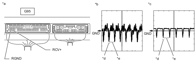
*a Component with harness connected
(Parking Assist ECU)
*b Waveform 1 (camera lens not covered, displaying an image) *c Waveform 2 (camera lens covered, blacking out the screen) *d Synchronization Signal *e Video Waveform - - Tech Tips
-
The video waveform changes according to the image sent by the side television camera assembly RH.
-
The video waveform is constantly output when the engine switch is on (ACC).
Measurement Condition Tester Connection Condition Tool Setting G95-38 (RCV+) - G95-17 (RGND) Engine switch on (IG), panoramic view monitor switch on 200 mV/DIV., 50 μsec./DIV. OK Waveform is similar to that shown in illustration. Result Proceed to OK NG -
OK
REPLACE PARKING ASSIST ECU Click here
NG
-
-
INSPECT OUTER REAR VIEW MIRROR ASSEMBLY RH
-
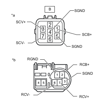
*a Component without harness connected
(to Side Television Camera Assembly RH)
*b Component without harness connected
(to Outer Rear View Mirror Assembly RH)
Disconnect the outer rear view mirror assembly RH connector.
-
Disconnect the side television camera assembly RH connector.
-
Measure the resistance according to the value(s) in the table below.
Standard Resistance Tester Connection Condition Specified Condition B-1 (SCB+) - 2 (RCB+) Always Below 1 Ω B-3 (SCV+) - 7 (RCV+) Always Below 1 Ω B-4(SGND) - 3(SGND) Always Below 1 Ω B-7 (SCV-) - 6 (RCV-) Always Below 1 Ω B-5 (SGND) - 1 (RGND) Always Below 1 Ω B-1 (SCB+) or 2 (RCB+) - Body ground Always 10 kΩ or higher B-3 (SCV+) or 7 (RCV+) - Body ground Always 10 kΩ or higher B-4(SGND) or 3(SGND) - Body ground Always 10 kΩ or higher B-7 (SCV-) or 6 (RCV-) - Body ground Always 10 kΩ or higher B-5 (SGND) or 1 (RGND) - Body ground Always 10 kΩ or higher Result Proceed to OK NG
NG
REPLACE OUTER REAR VIEW MIRROR ASSEMBLY RH Click here
OK
-
-
CHECK SIDE TELEVISION CAMERA ASSEMBLY RH
-
Replace the side television camera assembly RH with a new or normally functioning one.
-
Check if the same malfunction reoccurs when the side monitor screen is displayed.
Result Result Proceed to Malfunction does not reoccur (returns to normal) A Malfunction reoccurs B
A
END (SIDE TELEVISION CAMERA ASSEMBLY RH IS DEFECTIVE)
B
REPLACE PARKING ASSIST ECU Click here
-
-
CHECK HARNESS AND CONNECTOR (GVIF CABLE)
-
Replace the GVIF cable with a new or normally functioning one.
-
Check if the same malfunction reoccurs when the panoramic view monitor screen is displayed.
OK Malfunction does not reoccur (returns to normal). Result Proceed to OK NG
OK
END (GVIF CABLE IS DEFECTIVE)
NG
-
-
CHECK MULTI-DISPLAY
-
Replace the multi-display with a new or normally functioning one.
-
Check if the same malfunction reoccurs when the panoramic view monitor screen is displayed.
OK Malfunction does not reoccur (returns to normal). Result Proceed to OK NG
OK
END (MULTI-DISPLAY IS DEFECTIVE)
NG
REPLACE PARKING ASSIST ECU Click here
-